5-31
Fuel control unit and component
d. Install the fuel cup assembly. See “Fuel fil-
ter assembly” (6-6).
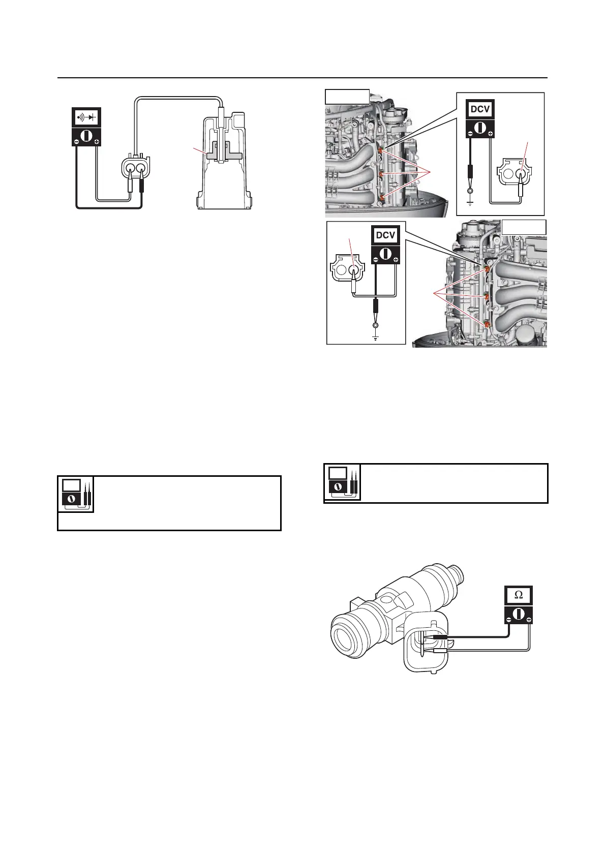
e. Connect the water detection switch cou-
pler.
Checking the fuel injector
1. Check:
• Fuel injector operation (using the YDIS
“Stationary test”)
No operating sound Check the fuel in-
jector input voltage.
2. Measure:
• Fuel injector input voltage
Out of specification Check the wire har-
ness for continuity.
a. Disconnect the fuel injector couplers “a”.
b. Turn the “POWER” switch to ON, and then
measure the input voltage between the
fuel injector coupler terminal and ground.
c. Turn the “POWER” switch to OFF.
d. Connect the fuel injector couplers.
3. Measure:
• Fuel injector resistance
Out of specification Replace.
a. Disconnect the fuel injector couplers.
b. Measure the fuel injector resistance.
c. Connect the fuel injector couplers.
Input voltage
12 V
Red/Yellow (R/Y)–Ground
1
B
Resistance (reference data)
11.50–12.50
PORT
R/Y
a
R/Y
a
STBD



 To Next Page