5-30
Fuel control unit and component
c. Turn the “POWER” switch to OFF, and
then disconnect the special service tool
and pressure pump.
d. Install the oil pressure sensor.
e. Connect the oil pressure sensor coupler.
Fuel control unit and component
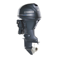
Checking the water detection switch
1. Measure:
• Water detection switch input voltage
Out of specification Check the wire har-
ness for continuity.
a. Disconnect the water detection switch
coupler “a”.
b. Turn the “POWER” switch to ON, and then
measure the input voltage at the water de-
tection switch coupler.
c. Turn the “POWER” switch to OFF.
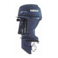
2. Check:
• Water detection switch continuity
Out of specification Replace the fuel
cup assembly.
a. Remove the fuel cup assembly. See “Fuel
filter assembly” (6-6).
b. Check that the float “1” moves smoothly.
Do not remove the clip and float.
c. Check the water detection switch for conti-
nuity when the float “1” is in positions “A”
and “B”.
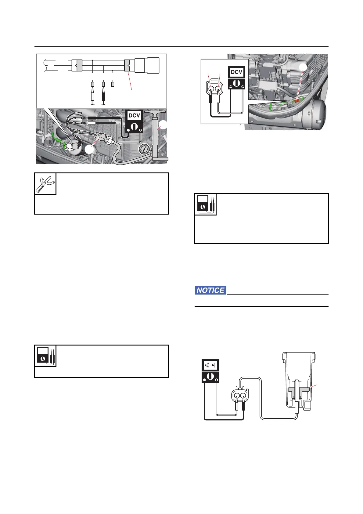
Pressure pump “1”
(commercially available)
Test harness EJ–ll–3 “2”
90890-06913
Input voltage
5 V
Blue/White (L/W)–Black (B)
P/W
Or
B
BG/W G
1
2
2
Water detection switch continuity
No continuity
Float position “A”
Continuity
Float position “B”
L/WB
a
1
A