7-4
Power unit (check and adjustment)
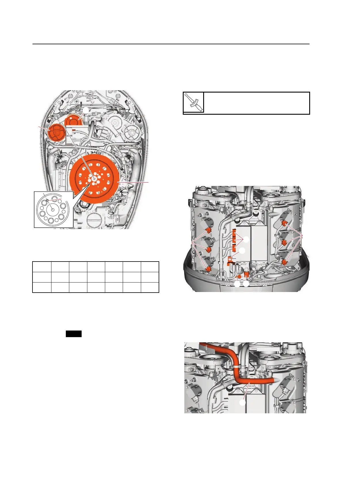
b. Turn the flywheel magneto “1” an addition-
al 360 clockwise until the dowel pin hole
“a” in the flywheel magneto “1” is aligned
between the VCT assembly (STBD) “2”
and driven sprocket (STBD) “3”.
c. Measure the intake and exhaust valve
clearances of the specified cylinders. Ad-
just if out of specification.
—: Not applicable
✔: Specified cylinder
9. Install:
•Gasket
• Cylinder head cover
See “Camshaft” (7-38).
• Timing belt guide (STBD)
10. Adjust:
• Timing belt guide clearance
See “Installing the timing belt” (7-35).
11. Install:
• Engine ECM bracket
• Engine ECM
• Spark plug
• Ignition coil
12. Install:
• Bracket “1”
13. Connect:
• Water pressure sensor coupler “a”
• Ignition coil coupler “b”
• Engine ECM coupler “c”
• Knock sensor coupler “d”
14. Install:
• PTT buzzer
• Canister
• Vapor gas hose
• Blowby hose “1”
#1 #2 #3 #4 #5 #6
IN — ✔✔✔——
EX — — — ✔✔✔
3
2
a
1
Spark plug
11 N·m (1.1 kgf·m, 8.1 lb·ft)
1



 To Next Page