Chapter 3 Hardware Overview
MES3500 Series User’s Guide
27
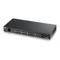
Figure 11 MES3500-24F Front Panel: DC Model
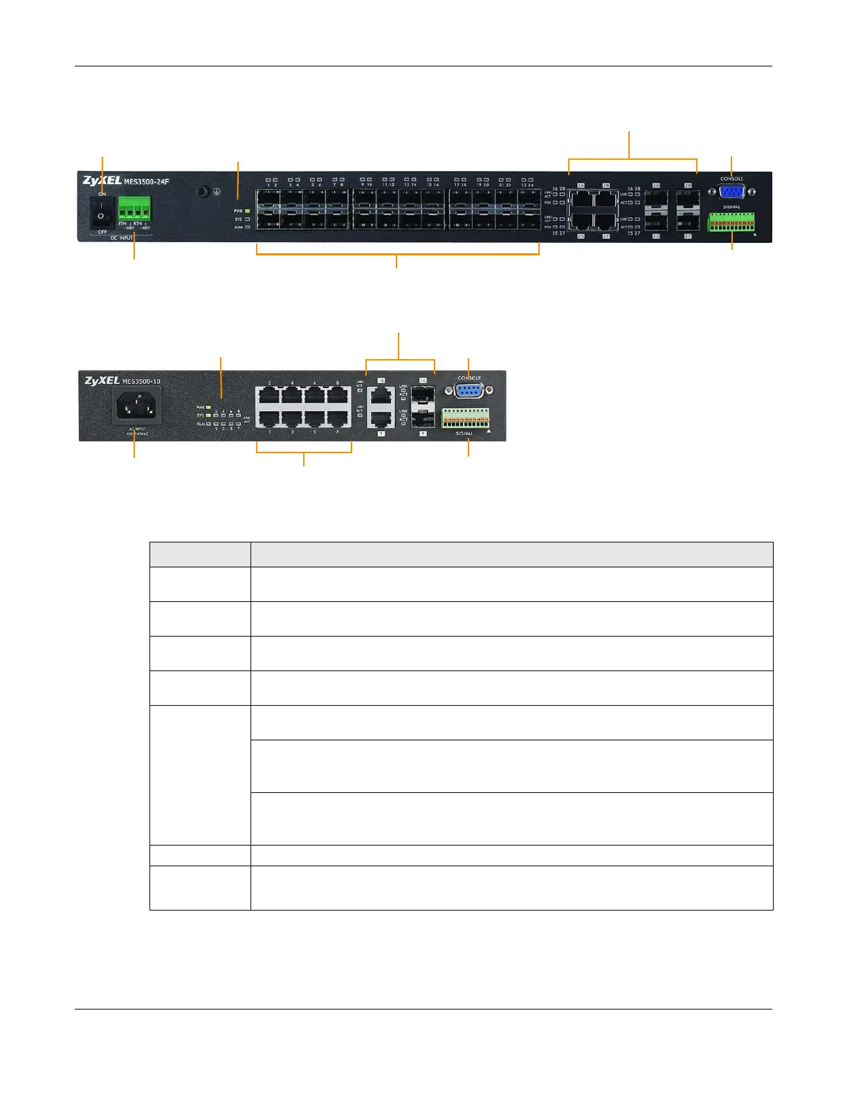
Figure 12 MES3500-10 Front Panel: AC Model
The following table describes the port labels on the front panel.
SFP Slots
Dual Personality Interfaces
Console Port
LEDs
Signal slot
Power Connection
Power Switch
Fast Ethernet Ports
Dual Personality Interfaces
Console Port
LEDs
Signal slot
Power Connection
Table 3 Front Panel Connections
LABEL DESCRIPTION
Power Switch This is for DC model only. After you connect the DC power properly (see Section 3.1.4.2 on
page 31.), put the power switch in the ON position to turn on the Switch.
Power
Connection
Connect an appropriate power supply to this port.
RJ-45 Ethernet
Ports
Connect these ports to a computer, a hub, an Ethernet switch or router.
SFP Slots Use transceivers in these slots for fiber-optic or copper connections to a computer, a hub, a
switch or router.
Four or Two
Dual Personality
Interfaces
Each interface has one 1000BASE-T RJ-45 port and one transceiver slot, with one port or
transceiver active at a time.
• Four 10/100/1000 Mbps RJ-45 Ports:
Connect these ports to high-bandwidth backbone network Ethernet switches using
1000BASE-T compatible Category 5/5e/6 copper cables.
• Four Transceiver Slots:
Use mini-GBIC or SFP transceivers in these slots for connections to backbone Ethernet
switches.
Console Port The console port is for local configuration of the Switch.
Signal slot Connect the signal input pins to signal output terminals on other pieces of equipment.
Connect the signal output pins to a signal input terminal on another piece of equipment.
 Loading...