Chapter 3 Hardware Overview
MES3500 Series User’s Guide
33
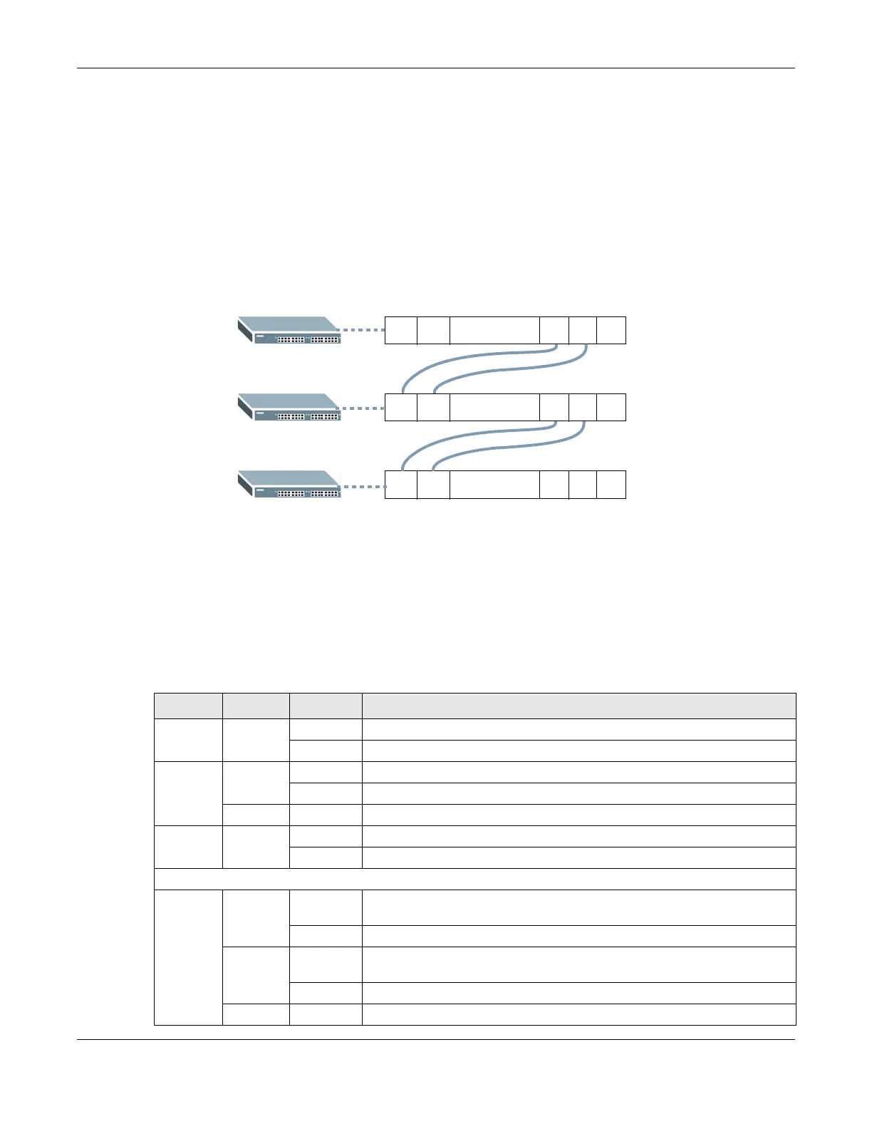
You can also daisy-chain the external alarm to another ZyXEL Switch which supports the external
alarm feature. If daisy-chaining to a ZyXEL switch that is a different model, check your switch’s
documentation for the correct pin assignments.
1 Use wires of the correct gauge to connect either of the signal output pin pairs (1-normal close, 2-
common) or (2-common, 3-normal open) on the Signal connector to the input signal pin pairs of
an Signal connector on another ZyXEL Switch.
2 When daisy-chaining further Switches ensure that the signal output pins you use are the same as
those you used when connecting to the first switch, as shown in the diagram below.
Figure 19 Daisy-chaining an External Alarm Sensor to Other Switches of the Same Model
3.2 LEDs
After you connect the power to the Switch, view the LEDs to ensure proper functioning of the
Switch and as an aid in troubleshooting.
12311 10
.........
12311 10
.........
12311 10
.........
Pin Assignments
Table 4 LED Descriptions
LED COLOR STATUS DESCRIPTION
PWR Green On The system is turned on.
Off The system is off.
SYS Green On The system is on and functioning properly.
Blinking The system is rebooting and performing self-diagnostic tests.
Off The power is off or the system is not ready/malfunctioning.
ALM Red On A hardware failure is detected, or an external alarm is active.
Off The system is functioning normally.
10/100 Mbps Fast Ethernet Ports (MES3500-24 & MES3500-10)
1 ~ 24
1 ~ 8
Green Blinking The system is transmitting/receiving to/from a 10 Mbps Ethernet
network.
on The link to a 10 Mbps Ethernet network is up.
Amber Blinking The system is transmitting/receiving to/from a 100 Mbps Ethernet
network.
On The link to a 100 Mbps Ethernet network is up.
Off The link to an Ethernet network is down.
 Loading...