Installation
146
Aastra 470 ab R3.0
syd-0337/1.5 – R3.0 – 05.2013
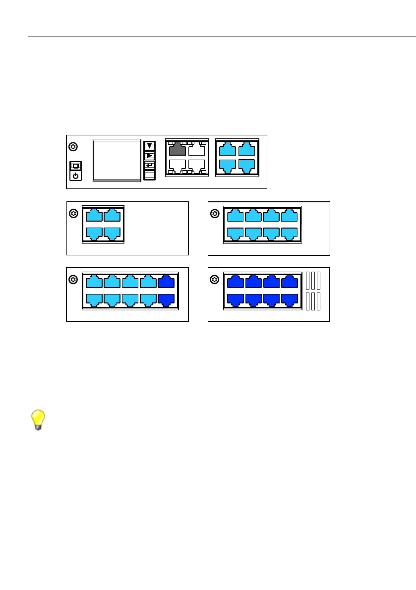
4. 7. 3. 3 FXS terminal interfaces
The Call Manager card CPU1 already contains 4 FXS terminal interfaces, which are
routed through to the front panel of the card and labelled accordingly. The number
of available FXS terminal interfaces can be increased by fitting interface cards. The
RJ45 connector assignment is identical. The possible RJ45 sockets are highlighted
in colour in the figure below.
Fig. 55 Connection possibilities for FXS terminal interfaces
On terminal cards with 16 or more interfaces some or all of the RJ45 sockets are
multiply assigned. The signals can be split again to individual RJ45 sockets using
patch cables and the fan-out panel FOP (see "Fan-out panel FOP", page 156) or with
8-fold assigned connecting cables (see e.g. "Prefabricated system cable 4 x RJ45",
page 115).
Tips
– Multiply assigned RJ45 sockets are colour-coded in blue.
– To be able to make emergency calls even in the event of a mains
power failure, you have the possibility of running up to 8 analogue FXS
lines via the EFOP emergency fan-out panel. In the event of a power
failure the EFOP switches the connected analogue phones automati-
cally and directly over to the analogue FXO exchange lines (see "Emer-
gency fan-out-panel (EFOP)", page 160).
'94
'94
'94
'94
8"/
-"/
-"/
'94
'94
'94
'94
-"/
FTD

 Loading...


