Installation
166
Aastra 470 ab R3.0
syd-0337/1.5 – R3.0 – 05.2013
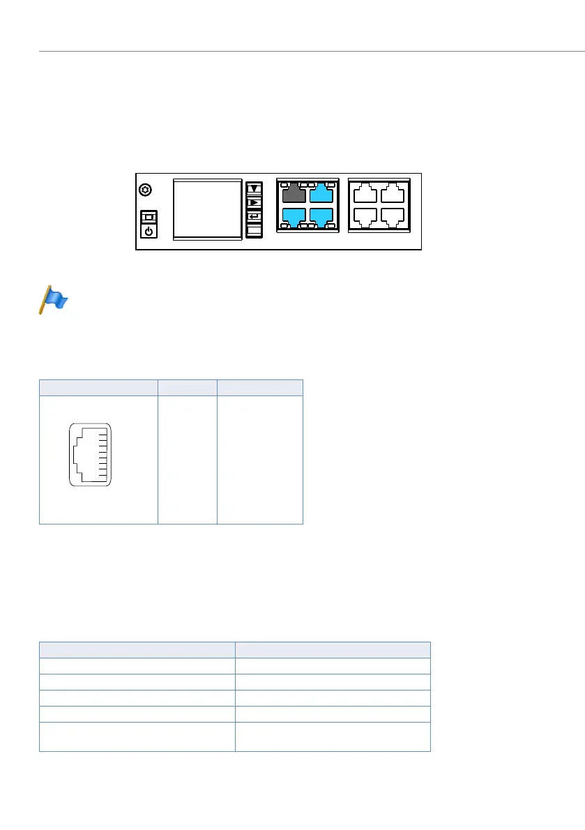
4. 7. 6 Ethernet interfaces
The communication server Aastra 470 has a Gbit Ethernet switch on the call man-
ager card. Three LAN interfaces are routed to the front panel of the call manager
card and labelled accordingly. The RJ45 sockets are highlighted in colour in the fig-
ure below.
Fig. 69 Connection possibilities for Ethernet interfaces
Note
Circuit type as per EN/IEC 60950: SELV
Connection
Tab. 73 Connection of Ethernet interfaces
Settings
The IP address can either be taken from a DHCP server in the IP network or config-
ured statically. If a DNS server is used, the communication server can also be ad-
dressed via its host name.
Tab. 74 Default values, IP address
RJ45 socket Pin Signal
1 TX D1+
2 TX D1–
3 RX D2+
4 BI D3+
5 BI D3–
6 RX D2–
7 BI D4+
8 BI D4–
Parameter Parameter value
IP address 192.168.104.13
Subnet mask 255.255.255.0
Gateway 0.0.0.0
DHCP Yes
Host name <Model name>-<MAC address>
1)
Example: Aastra430-00085d803100
1)
This entry is hidden and does not appear in the parameter’s input field
8"/
-"/
-"/
'94
'94
'94
'94
-"/
FTD

 Loading...


