Expansion Stages and System Capacity
43
Aastra 470 ab R3.0
syd-0337/1.5 – R3.0 – 05.2013
3. 2. 1 Interfaces, display and control elements
The interfaces accessible from the outside are located on the front and rear side of
the basic system. The housing cover only needs to be opened when fitting an addi-
tional fan (see "Fitting an additional fan", page 98).
Basic system (without call manager card)
The figure below shows the positions of basic system interfaces without call man-
ager card.
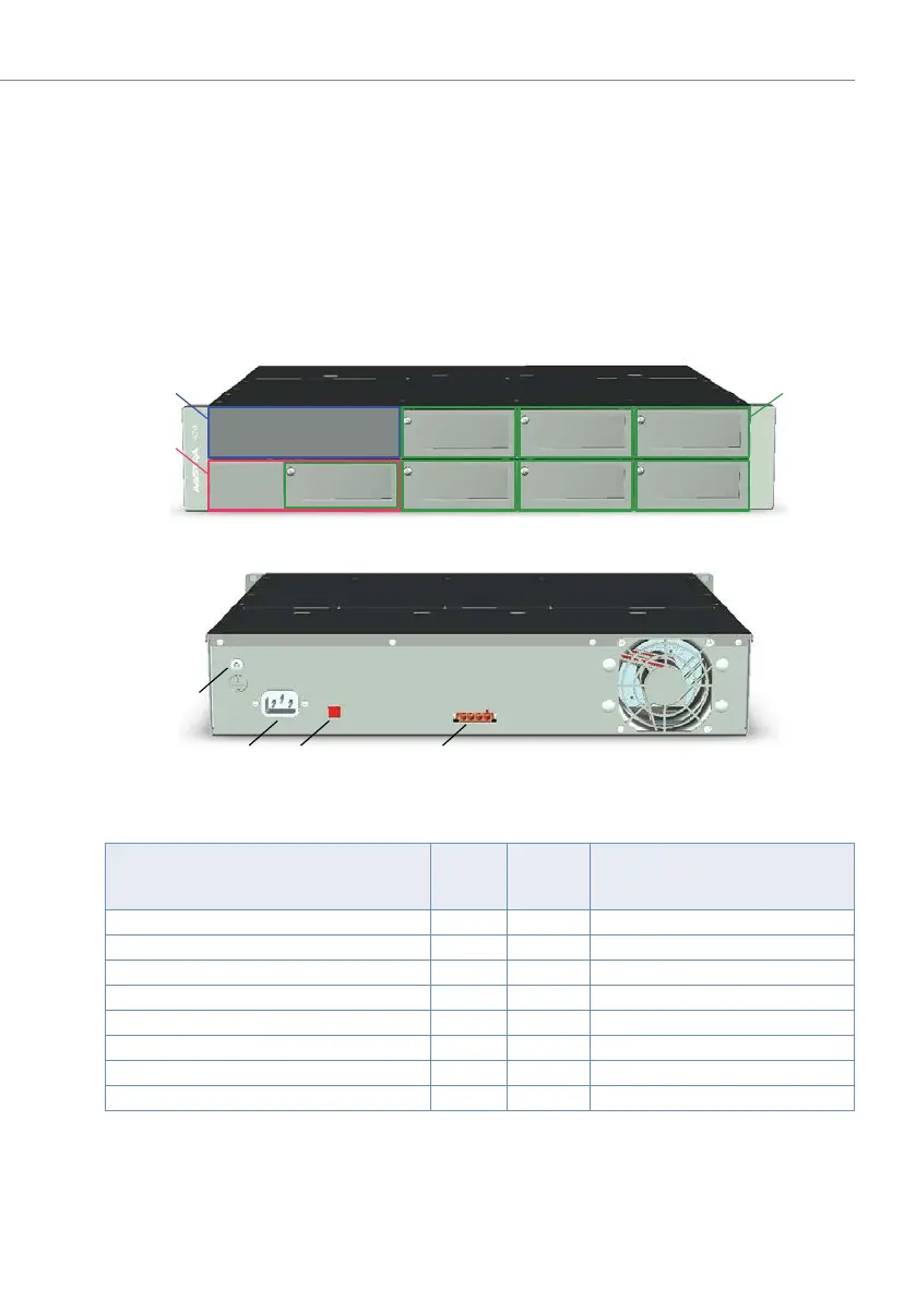
Fig. 8 Position of the interfaces on the basic system
Tab. 12 Interfaces of the basic system
Interfaces
Number
of
entries
Position Remarks
Slot for Call Manager card CPU1 1 [1] Device ships already equipped
Slot for application card CPU2 1 [2] Can be fitted as an option
Slots for interface cards 7
1)
1)
1 fewer slot if CPU2 application card is fitted
[3] Can be fitted as an option
Interface for redundant fan unit 1 Connectors inside the housing
Earth connection 1 [4]
Mains socket for 115/230V power supply input 1 [5]
Voltage converter 115/230 V 1 [6]
Socket for auxiliary power supply unit APS2 1 [7]
[4]
[3]
[2]
[1]
[6][5] [7]

 Loading...


