Installation
93
Aastra 470 ab R3.0
syd-0337/1.5 – R3.0 – 05.2013
4 Installation
This Chapter tells you the ways in which Aastra 470 can be installed and the
conditions to be observed. It also includes the mounting into a 19” rack, the
correct way to connect the earthing, and the power supply. Other topics in
this chapter include how to fit system modules and interface cards. Finally the
Chapter also describes the network- and terminal-side connection of the in-
terfaces and the installation, powering and connection of system terminals.
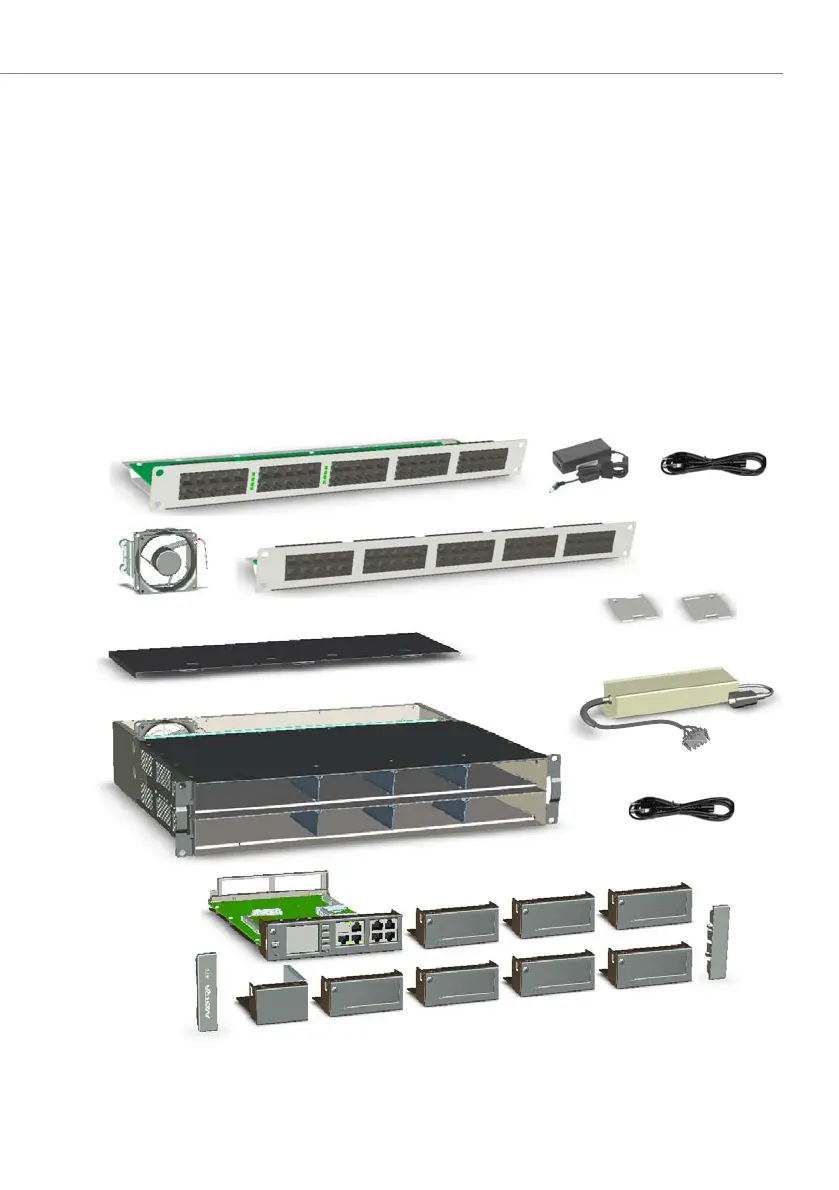
4. 1 System components
The figure below shows the components of the Aastra 470 communication server
complete with mounting options.
Fig. 17 System components with mounting options
Mounting plates for auxiliary power
suply unit
Aastra 470 basic system housing
Fan-out panel FOP
Screw covers
on the right
Auxiliary power suply unit
(APS2)
Dummy covers
Call Manager
card CPU1
upper, rear cover
Screw covers
on the left
Redundant fan unit
(RFU)
Power cord
Fan-out-panel EFOP
Power supply EFOP
Power supply unit with
power cord

 Loading...


