Installation
178
Aastra 470 ab R3.0
syd-0337/1.5 – R3.0 – 05.2013
Ambient conditions
• When installing: Ensure convection (space for ventilation).
• Avoid excessive dust.
• Avoid exposure to chemicals.
• Avoid direct sunlight.
• See also technical data in Tab. 135.
Note:
If these requirements cannot be met (e.g. outdoor installation), use the
appropriate protective housing.
4. 8. 2. 1 Installing the radio units
Do not remove the cover of the radio unit. (Warranty protection will lapse if the
cover is removed)
Fit the mounting bracket (see Fig. 74 dimensional drawing for wall mounting). Ob-
serve the minimum distances (see Fig. 75).
Position the DSI socket(s) near the radio unit.
Each radio unit requires one DSI bus (two optional on the SB-8): Do not connect
any other terminals.
The radio units can be powered from the communication server up to the maxi-
mum line length of 1200 m specified for operation (wire diameter 0.5 mm). The
plug-in power supply unit for is the same as the one for the Office 135 charging
bay.
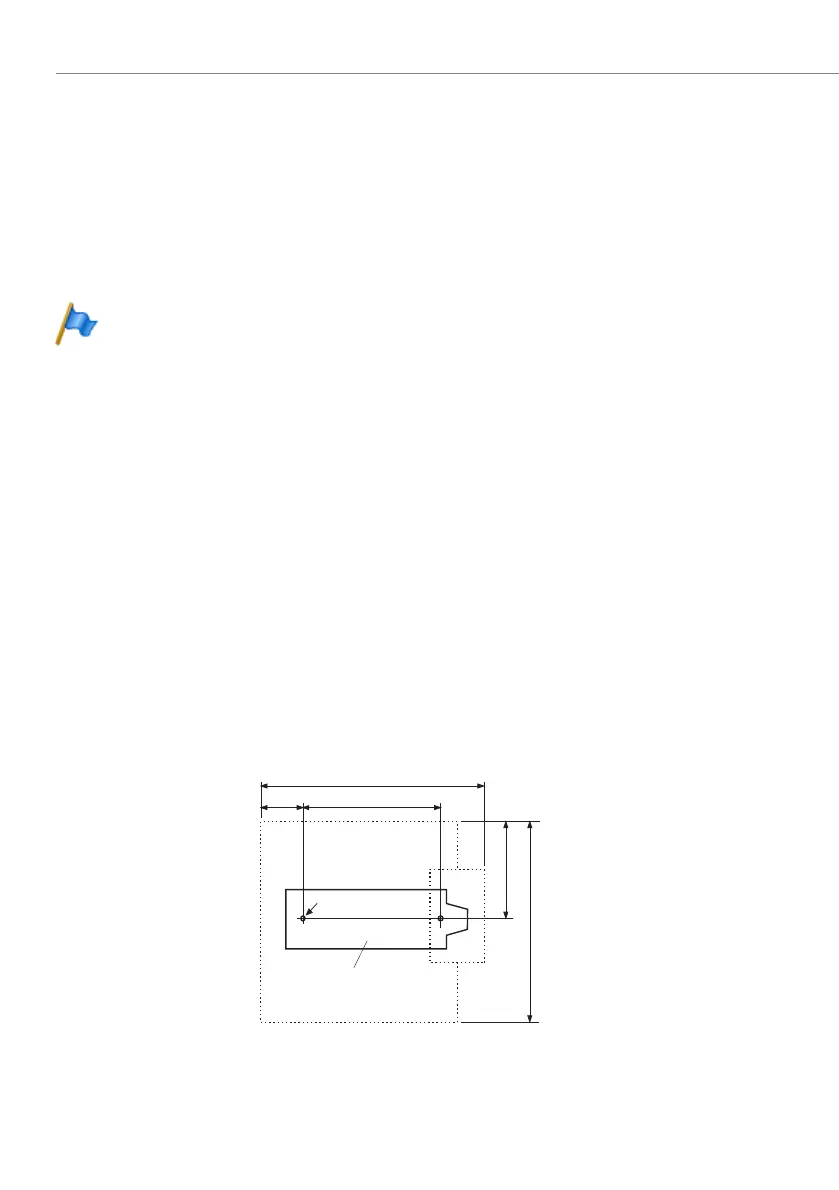
Fig. 74 Dimensional drawing for wall-mounting the mounting bracket
160
100
37
84
168
Mounting bracket
ø screw : 4 mm
All dimensions in mm

 Loading...


