Operation and Maintenance
240
Aastra 470 ab R3.0
syd-0337/1.5 – R3.0 – 05.2013
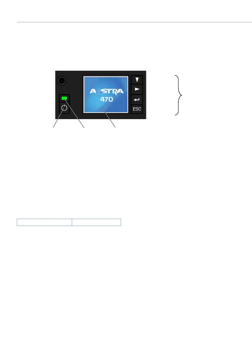
6. 4 Display and control panel of the call manager
The display and control panel on the call manager card consists of the colour dis-
play with the navigation keys and the On/Off button with integrated status LED. It
is used to indicate operating states and carry out functions.
Fig. 84 Aastra 470 display and control panel
6. 4. 1 PIN control panel
A number of functions executed via the navigation keys require a PIN (e.g. run first
start).
The PIN always consists of 4 digits and can be modified via AMS in the access con-
trol using the SystemUserInterface user account:
Tab. 94 Default PIN control panel
It is advisable to change the PIN immediately to prevent unauthorized access to the
communication server.
6. 4. 2 On/Off key
Pressing the On/Off button starts up the call manager (which is switched off).
In normal operation a short key press of the On/Off key brings up the Shut Down
menu, offering the choice of shutting down the Call Manager, the application
server or the entire communication server. The navigation keys are used to select
from the menu.
Default PIN 4321
Escap key
Enter key
Right key
Downwards key
Colour display 1.8”
Status LED call
manager
On/O key
Navigation
keys

 Loading...


