Operation and Maintenance
270
Aastra 470 ab R3.0
syd-0337/1.5 – R3.0 – 05.2013
6. 6. 2. 4 Operating state of the Aastra DECT radio units
Each radio unit is equipped with 3 LEDs. The operating state the radio units is indi-
cated by different colours and flashing sequences in cycles of 1 s, specifically by
one of the two outer LEDs on the SB-4+ and by both outer LEDs on the SB-8 / SB-
8ANT (separately for each DSI bus). Each character (G, R or -) corresponds to 1/8 of a
second.
Example:
During the synchronization phase GGGGRRRR the LED flashes periodically
1/2second green, 1/2second red.
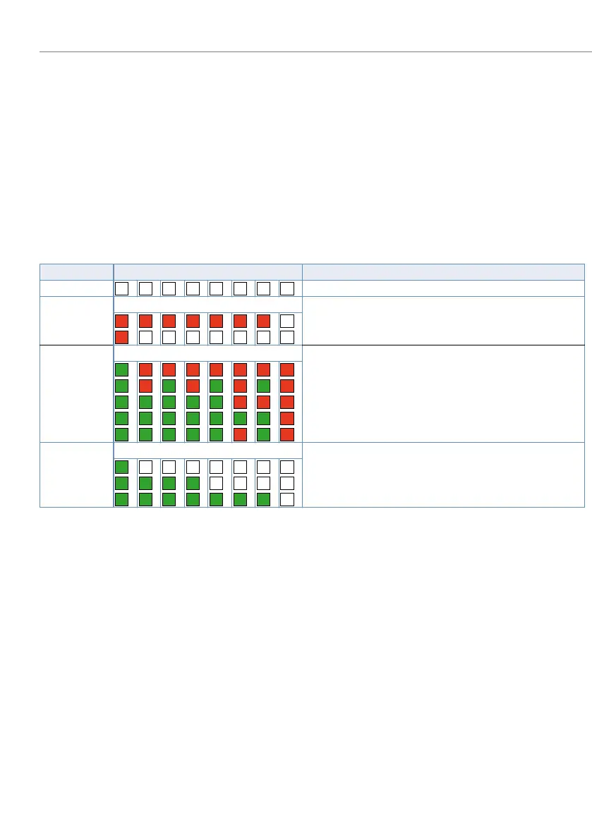
Tab. 107 Flashing sequences of the status LED on the DECT radio unit
An orange status LED indicates that the DECT signalling is active, i.e. DECT se-
quences are currently being transmitted between the cordless phone and the radio
unit. Examples:
• With each keystroke on the cordless phone the LED briefly lights up orange.
• During a cordless phone software download the orange LED remains lit until the
download is completed.
State Cycle Meaning
No flashing LED switched off / software not running/RU not connected
Red Error:
DSI bus not in order
Power supply error or DSI line too long
Green / red Startup process:
DSI ok
Software downloading
Synchronizing
Starting DECT
HF Power Down/DECT System Status Passive
1)
1)
This operating state appears in the following situations:
- during a configuration data upload
- After a system first-start
- If the parameter DECT system state is set to Passive in the AMS Configuration Manager
- If a radio unit is not allocated to a Location Area (this may happen after adding a radio unit to a system with several Loca-
tion Areas, which is the case when a radio unit has already been set in a Location Area unequal 0). In this case the added ra-
dio unit has to be manually allocated to the selected Location Area.)
Green Normal operation (requirement: LED not switched off):
All B channels available
1 to 3 B channels busy
> 3 B channels busy
– – – – – – – –
R R R R R R R
–
R
– – – – – – –
G R R R R R R R
G R G R G R G R
G G G G G R R R
G G G G G G G R
G G G G G R G R
G
– – – – – – –
G G G G
– – – –
G G G G G G G
–

 Loading...


