Operation and Maintenance
243
Aastra 470 ab R3.0
syd-0337/1.5 – R3.0 – 05.2013
6. 4. 3. 3 Error display with status LED
Errors that occur during the start-up phase1 are indicated with the status LED.
Tab. 99 Error displays during system setup 1:
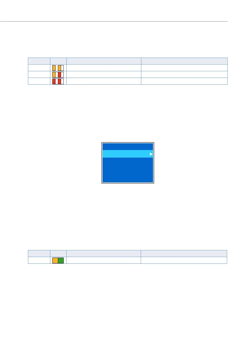
6. 4. 3. 4 Boot menu
The boot menu is shown during the start-up phase 2 (LED pattern 5 in Tab. 97) dur-
ing approx. 3 seconds. The boot menu allows the user to reset the IP address data
or to carry out a first start. The boot mode is exited automatically and the startup
then continues normally if no input is made within 3 seconds.
Fig. 85 Boot menu Aastra 470
6. 4. 3. 5 Display of event messages
If an event message occurs in normal operation, the LED pattern switches from
"slowly flashing green" to "slowly flashing orange-green" and the event message is
indicated on the colour display.
Tab. 100 Display of event messages in normal operation:
6. 4. 3. 6 Status LEDs on Ethernet interfaces
For explanations of the status LEDs on Ethernet interfaces see "Status LED",
page 168.
Pattern LED Duration Meaning
7 As long as the error remains RAM test faulty
8 As long as the error remains Boot software missing
9 As long as the error remains CRC test boot software faulty
Pattern LED Duration Meaning
11 As long as the event message exists Event message present
––
O
O
––
O
R
––
RR
#PPUNFOV
4FU*1EFGBVMUT
'JSTUTUBSU
O
G

 Loading...


