Operation and Maintenance
260
Aastra 470 ab R3.0
syd-0337/1.5 – R3.0 – 05.2013
6. 6. 1. 3 Signal destinations
6 signal destinations can be configured in the Fault & Maintenance Manager. Any
one of the six event tables can be assigned to each signal destination.
When a communication server is first started, one event table with its own number
is assigned to each signal destination.
Signal destinations include:
• System phones with alphanumeric display)
• External signal destination (signal destination PC via ISDN or LAN/WAN to T in-
terface)
• Local signal destination (e.g. PC / printer, PC to S interface/Ethernet interface)
• Event log (event protocols in the Fault & Maintenance Manager)
• Internal or external e-mail destinations
• ATAS interface (e. g. fpr alarm server)
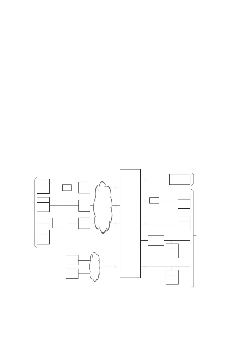
There are several possibilities for connecting the signal destinations with a commu-
nication server:
Fig. 88 Overview of connection possibilities for the various signal destinations
V.24
V.24
S
SS
S
S
S
S
S
PC
PC
PC
PC/T
COM-
Port
PC
ISDN-
Card
PC
COM-
Port
PC
ISDN-
Card
ISDN-
Gateway
DSI
Ethernet
Ethernet
T
T
T
LAN
LAN
LAN
TA
RTS/CTS
TA
ISDN-
Gateway
RTS/CTS
SMTP-
Server
NT1
NT1
NT1
ISDN
IP
E-mail
destina-
tion
internal or
external
Local
signal
destina-
tions
Signal
Destina-
tion:
terminal
System
Terminals
Communica-
tion server
External
signal
destina-
tions

 Loading...


