Expansion Stages and System Capacity
41
Aastra 470 ab R3.0
syd-0337/1.5 – R3.0 – 05.2013
operating reliability. If the internal power supply unit fails, the external auxiliary
power supply unit takes over the power supply.
3. 2 Basic system
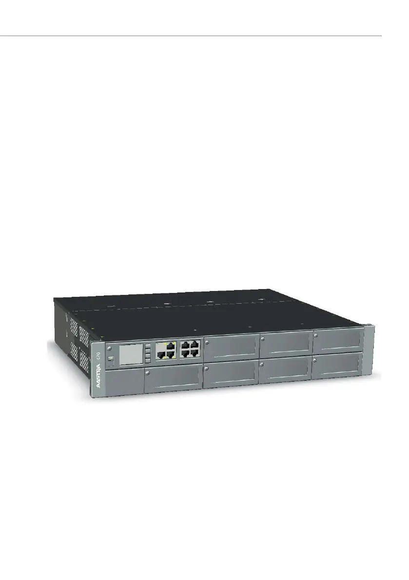
The Aastra 470 basic system consists of the following components:
• Metal housing (2 height units) suitable for installation in a 19" rack or for desktop
installation.
• CPU1 call manager card, fitted with a Flash card, a RAM module and an EIM card.
• 7 expansion slots with dummy covers fitted
• BP2U backplane fitted to electrically connect processor cards and interface
cards.
• Fitted PSU2U power supply unit
• Fitted fan
• Power cord
• Rack assembly material
Fig. 6 Aastra 470 basic system
For electrical and thermal reasons the dummy covers must always be fitted. They
are removed only to expand the basic system with interface cards or an application
card.
For a clearer overview the figure below shows the open communications server
from above with an additional fan fitted. The housing cover is in two parts. The up-
per, rear cover is removed for the purpose of fitting an additional fan (see "Fitting
an additional fan", page 98 for the procedure).

 Loading...


