Operation and Maintenance
242
Aastra 470 ab R3.0
syd-0337/1.5 – R3.0 – 05.2013
6. 4. 3. 1 Startup and operating state display
In the system setup the status LED indicates the current operating state of the Call
Manager.
The start-up phase can be divided into three parts:
System setup 0:
In this phase, the system can be set to the boot mode (see "Boot mode", page 242)
System setup 1:
The colour display is not yet operational. Any errors that occur are indicated with
the status LED (see "Error display with status LED", page 243).
System setup 2:
The colour display is operational. In this phase, the boot menu is shown (see "Boot
menu", page 243). Any errors that occur are displayed via the colour display.
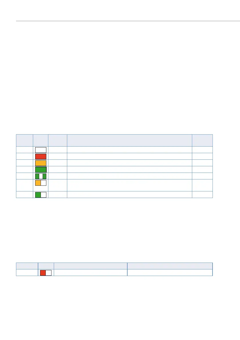
Tab. 97 Display pattern at system setup
6. 4. 3. 2 Boot mode
The boot mode enables an Emergency Upload via the Ethernet interface (EUL via
LAN). This is required whenever there is no longer any executable system software
stored on the communication server for whatever reason.
The boot mode is indicated by the status LED flashing red.
Tab. 98 Display pattern in the boot mode
To access the boot mode press the enter key during the LED test red, which is exe-
cuted during the start-up phase 0.
The boot mode remains active until the Emergency Upload is completed or the sys-
tem is restarted manually.
Pattern LED
Dura-
tion [s]
Meaning
Start-up
phase
0 steady Call manager is switched off
1 ~1,5 Red LED test 0
2 ~1,5 Orange LED test 0
3 ~1,5 Green LED test 0
4 ~4 RAM test, load boot software, boot software CRC test 1
5 ~10 Boot software running, load system software, system software CRC
test
2
6 steady System software running error-free
Pattern LED Duration Meaning
10 As long as the boot mode is active Boot mode active
–
R
O
G
–
G
G
–
O
–
G
–
R

 Loading...


