Installation
163
Aastra 470 ab R3.0
syd-0337/1.5 – R3.0 – 05.2013
Connection
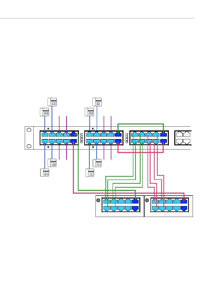
The EFOP fan-out-panel comprises 5 connection blocks of 10 RJ45 sockets each.
The line switchover is carried out on the two left-hand connection blocks. The
three right-hand connection blocks are used for separating the four-fold assigned
RJ45 sockets FXS 1-4 and FXO 1-4.
On FXS or FXO interface cards with four-fold assigned RJ45 sockets, direct wiring to
the FXS 1-4 and FXO 1-4 sockets of the EFOP fan-out-panel is possible. The unas-
signed connection blocks can be used for other purposes.
The diagram below shows the connection between an EFOP fan-out-panel and 8
emergency phones and 8 analogue exchange lines.
Fig. 67 Connection of EFOP fan-out-panel (example)
The patch cables are available separately in lengths of 1 and 2 m (see "Equipment
Overview", page 279).
The internal wiring of the 3 right-hand connection blocks is the same as for the FOP
fan-out-panel (see Tab. 71).
1
3
42
1
2
3
4
1
2
3
4
16FXO
EFOP
1
3
5
7 9
-12
8 13-16642
1
3
5
7
2
4
6
8
16FXS
1
3
5
7 9
-12
8 13-16642
PSTN PSTN
PSTN PSTN
1
PSTN
3
FXS 1-4 1
3
5
7 1-4
3
1
1
PSTN
3
FXS 1-4
3
1
2
PSTN
4 8 5-864242
FXO 1-4
2
PSTN
442
FXO 1-4

 Loading...


