Expansion Stages and System Capacity
47
Aastra 470 ab R3.0
syd-0337/1.5 – R3.0 – 05.2013
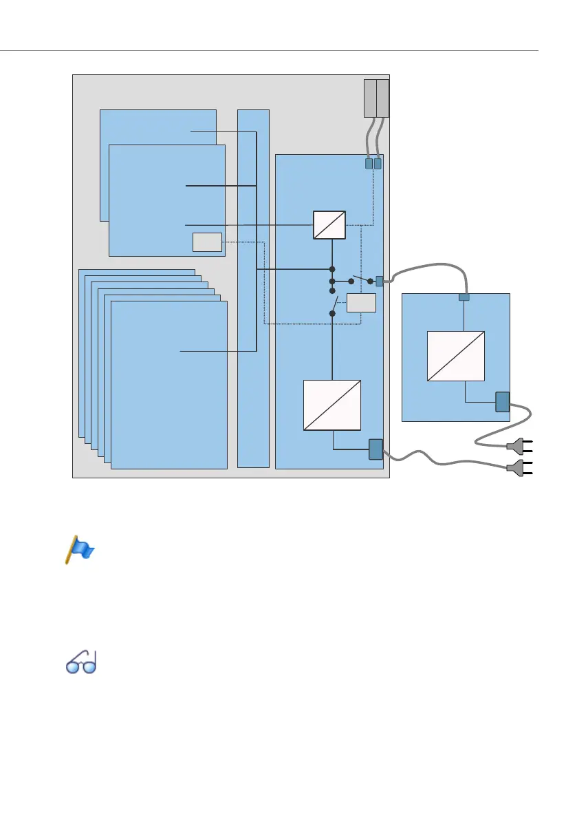
Fig. 10 Overview of the Aastra 470 power supply concept
Notes
– It is also possible to operate the communication server with the exter-
nal power supply unit APS2 only In this case redundancy operation is
of course no longer possible.
– To ensure that its operation is maintained even in the event of a mains
outage, an external uninterruptible power supply (UPS) must be used.
See also:
For the available power outputs using the various types of power supply
and for connecting the power supplies, see "Powering the communica-
tion server", page 103.
=
~
=
~
=
=
24 VDC
control
24 VDC
3.3 VDC
control
3.3 VDC
CPU1
CPU2
24 VDC
24 VDC
24 VDC
24 VDC
Mains power
115/230 VAC
Power
control
section
Aastra 470 housing
Redundant
fan unit
Standard fan
Interface cards
Auxiliary
power
suply unit
Internal power suply unit
Backplane

 Loading...


