Expansion Stages and System Capacity
64
Aastra 470 ab R3.0
syd-0337/1.5 – R3.0 – 05.2013
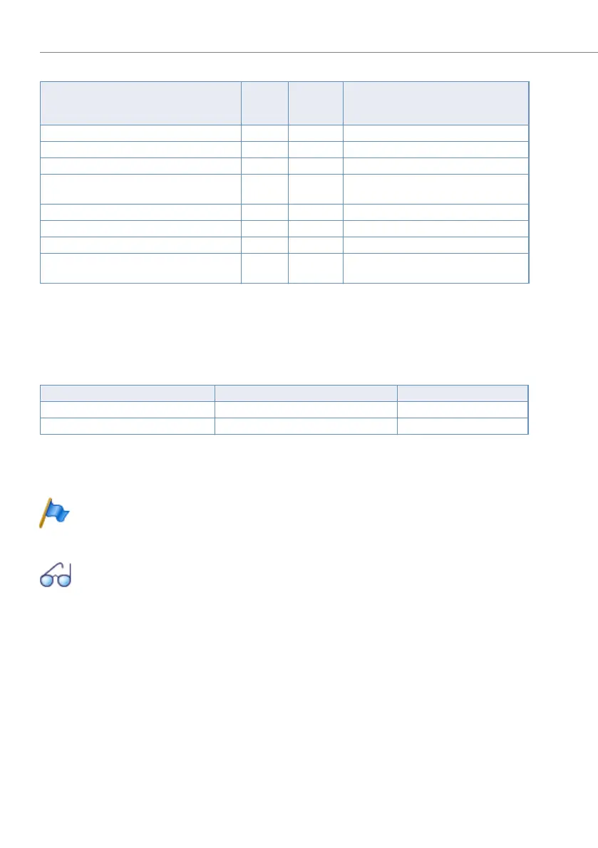
Tab. 26 Interfaces, display and control elements of the applications card
The meaning of the status LEDs is explained in the chapter "Display and control
panel of the application server", page 245.
The maximum permissible current input at the USB interfaces varies:
Tab. 27 Max. admissible current input at USB interfaces
Access to the applications server is normally via the WebAdmin configuration tool,
which means the front-side interfaces of the applications card are not needed.
Note
For licensing reasons the front-side connections are to be used for main-
tenance purposes only. Installing user-specific applications is prohibited.
See also:
Informations about the installation, configuration and software update of
the applications card can be found in the Installation Instructions for the
CPU2 application card.
Interfaces, display and control elements
Number
of
entries
Position Remarks
On/Off button with integrated status LED 1 [1]
Ethernet interface 1Gbit/s 1 [2] No provision for use at present
USB interfaces 2.0 4 [3] For connecting the keyboard, mouse, etc.
Status LEDs 2 [4] For indicating HDD access and USB sup-
ply overload
VGA video interface 1 [5] For connecting the monitor
Processor module with standard PC 1 [6]
>160GB hard disk 1 [7]
USB interfaces 2.0 for "software dongles" 2 [8] One of the interfaces is taken up by the
TWP application (CPU2)
Front-side USB interfaces Internal USB interfaces Max. current input [mA]
top left / bottom left bottom 100
top right / bottom right top 500

 Loading...


