120 XFC G4 2103335 Rev AB
Collect the data from the unit, see section 6.2.1, Data collection, on page 108.
Back up the configuration files see section 6.2.2, Back up configuration files (save), on page 108.
Ensure the J13 (Figure 86) memory backup jumper covers the top two pins.
Verify “LL” battery alarm is not being displayed on the LCD.
Measure the lithium battery with a Multi Meter and ensure it is > 3.0V.
Disconnect the battery charger from the panel terminals EXT CHGR +/- J5 (Figure 86, XFCG4 Electronic Board
Maintenance Connections, page 114).
Disconnect the Battery Cable from the panel connector J1 (Figure 86).
CAUTION – Equipment Damage. Gently spread the tabs with fingers. Do not use tools. Engine card damage
may result.
Spread the connector fingers extending down from the CPU engine card connector. The engine card will spring up at
a 30 degree angle from the main board.
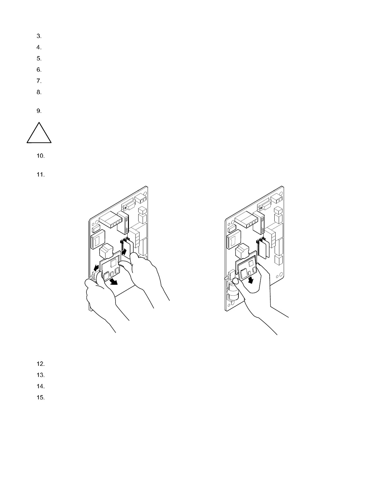
Pull the engine card out (Figure 90).
Figure 90: CPU Engine Card Removal
Insert the new engine card at a 30 degree angle (Figure 91).
Press the engine card in until the gold plated edge connector pins at the top of the engine card are no longer visible.
Press the engine card down toward the main panel until a click is heard.
Restore station files as described in section 6.2.3, Restoring configuration files (Restore), on page 109.