30 XFC G4 2103335 Rev AB
Important Note: When connecting or disconnecting any wires to the flow computer board, all power sources
should be removed, and insure that the equipment is properly grounded.
When the digital output is used as a measurement device, AGA-3, AGA-7 or liquid measurement, the outputs can be set when
the following conditions occur:
— Differential pressure over high limit
— Volume set point
— Differential pressure under low limit
— Flow temperature low
— Static pressure over high limit
— Flow temperature high
— Static pressure under low limit
— Flow rate low
— Low charger voltage
— Flow rate high
— Remote sense is on
— Trip on digital input
— Custom programmable by Totalflow or user-programmable with IEC 1131 programming language
3.6.3.1 Electrical Specification (Each Point)
— Open circuit voltage: 0 Vdc
— Short circuit leakage current: 0 uA typical
— Output capacitance: 1000 pF typical
— Maximum allowable voltage range on output: 0.5 Vdc to 26.5 Vdc
3.6.3.2 Input Specification
— Open drain FET type
— “ON” resistance (Including PTC fuse resistance): 0.1 Ω typical
— Maximum pulse current: 3 A for 5 seconds
— Maximum continuous sink current: 2 A
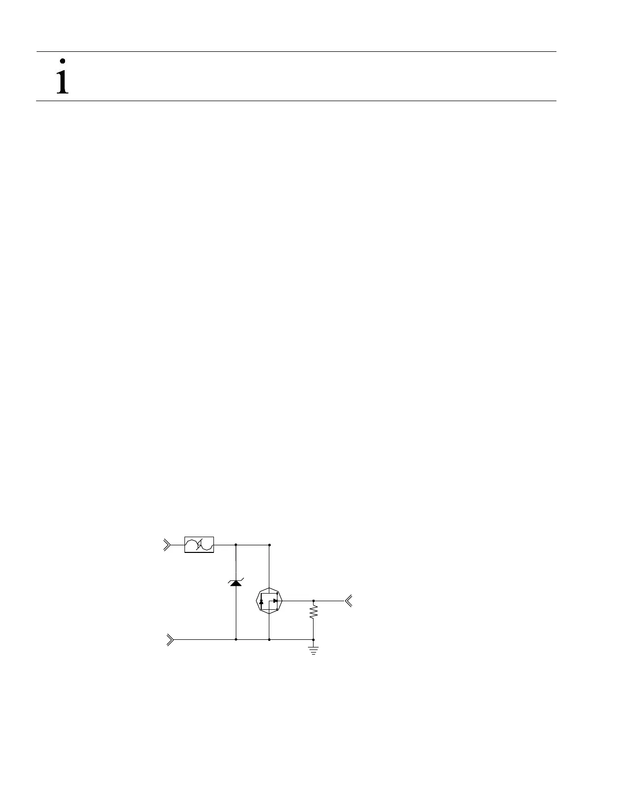
Figure 10 Typical Point Schematic
2.5A
24V
GND
SIG
OUTPUT CONTROL