149 XFC G4 2103335 Rev AB
Clip the negative lead of the MM to the other side of the test resistor.
Determine if the loaded voltage is greater than or equal to the specification listed in Table 18:.
- If solar panel is not above the minimum.
- Replace solar panel.
- Retest.
Return to the Power Troubleshooting flowchart and continue testing, if the issue still exists.
Table 18: Specifications for Solar panels
7.3.4 AC Charging System Test
If the system setup includes an ac charger connected to the flow computer, and it is not supplying the required voltage to the
unit, it may be necessary to test the ac charger.
7.3.4.1 Step by Step Instructions
To perform a test on the ac charging system:
Verify that all the wiring is correct:
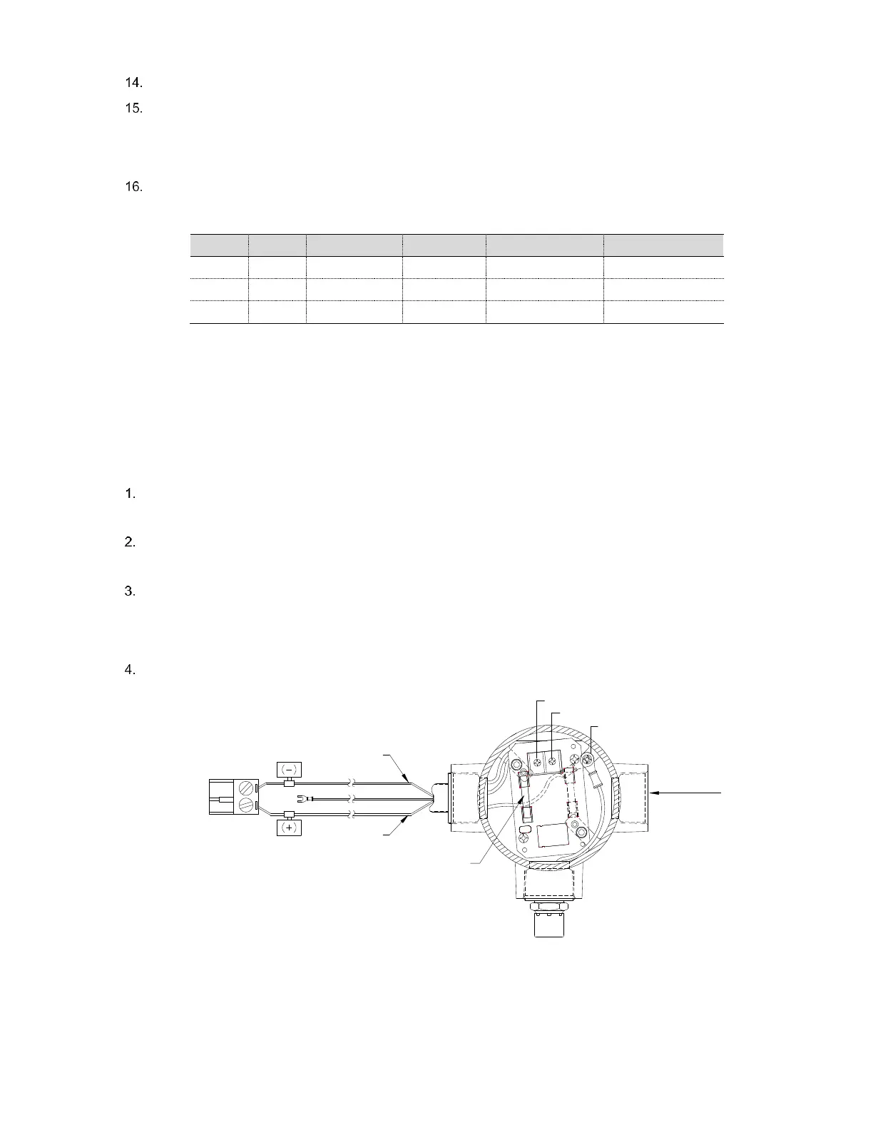
- Check the dc wiring to the J5 charger input termination block connector (Figure 99:).
Verify the primary ac voltage input level is correct.
- Check the input ac power supply voltage to the external ac charging unit.
Verify the dc output from the charger.
- If there is no dc output from the charger, replace charger fuse (Figure 99:).
- If the fuse is not faulty, or there is no charger dc output voltage after replacing the fuse, replace the ac charging
unit.
If an issue still exists, return to the Power Troubleshooting flowchart and continue testing.
REPLACEABLE
F2-2AMP FUSE
AC - HOT
AC - GROUND
AC - NEUTRAL
AC IN
GROUND TO ENCL.
BLK
RED
J17 CHARGER
INPUT
CONNECTOR
Figure 99: AC-DC Charger Wiring Instructions
7.3.5 Auxiliary Equipment Isolation Test
This test will need to be performed if your battery pack output voltage is not remaining consistent and no errors were found
during the previous Power Supply, Solar Panel Charging System or AC Charging Circuit troubleshooting tests.