157 XFC G4 2103335 Rev AB
Measure voltage at J4 between: pin-1 (GND) and pin-3 (SWVBAT) using a MM set to volts DC. Voltage should be
greater than 11.9Vdc. If voltage is equal to or less than 11.9, return to test sequence outlined in the Power
Troubleshooting flowchart (Figure 97:).
Measure voltage at J4 between: pin-1 (GND) and pin-2 (VBAT) using a MM set to volts DC. Voltage should be greater
than 11.9Vdc for this unit. If voltage is equal to or less than 11.9, return to test sequence outlined in the Power
Troubleshooting Flowchart (Figure 97:).
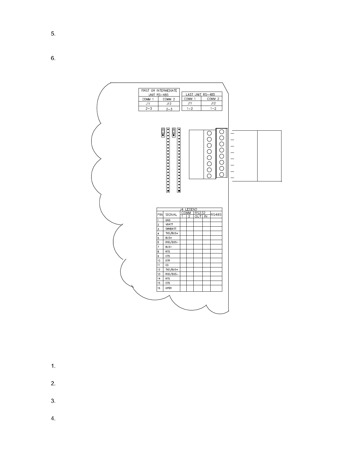
Figure 103: XFC
G4
Communication Wiring
7.4.4 Transceiver Check
To perform a transceiver check:
If available, use a wattmeter to check transceiver output power. Refer to manufacturer’s documentation for measuring
instructions.
If available, use two hand-held transceivers, and verify communication path between master and remote sites. Voice-
activated interface can be used, if available.
Verify that transceiver is set to the correct frequency. Refer to manufacturer’s documentation for checking frequency
instructions.
If a directional antenna is used, verify the orientation to the antenna to the master site.
1
1
XA1
A
J4
1
J12
3
J11
1
3
COMM 2
COMM 1
B
COMM1
XA2
COMM2
1
4
3
2
5
6
7
8
9
16
15
14
13
12
11
10
GND
AB
RTS
BUS-
RXD/BUS-
SWVBATT
VBATT
BUS+
CTS
DTR
CD
TXD/BUS+
RXD/BUS-
RTS
CTS
OPER
TXD/BUS+