148 XFC G4 2103335 Rev AB
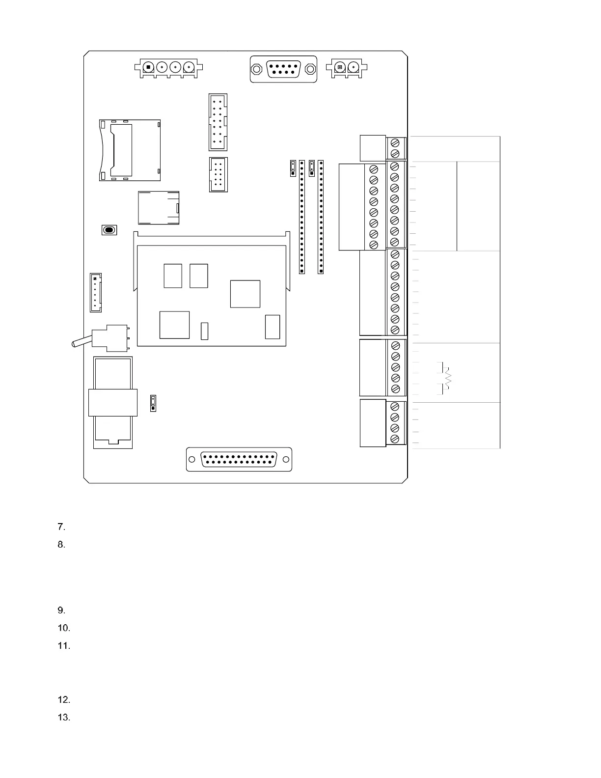
Figure 98: XFC
G4
Main Electronic Board
Measure the solar panel voltage at the connector using a MM
Connect the (+) and (-) leads to the (+) and (-) solar panel wires. Loaded voltage should be greater than or equal to
the specification listed in Table 18:
- If the solar panel is not above minimum.
- Replace the solar panel.
- Retest.
Disconnect the solar panel from the circuit board.
Set the MM range to read over 20 Vdc.
Determine if the Open Circuit voltage is greater than or equal to the specification listed in Table 18:,
- Clip the positive lead of the MM to positive wire.
- Clip the negative lead of the MM to negative wire.
- If solar panel is not above the minimum voltage, continue to the next step.
Attach the selected resistor from Table 18: between the two solar panel wires.
Clip the positive lead of the MM to the one side of the test resistor.
SECURITY
OFF
KEYPAD
ON
J16
S1
XIMV INTERFACE
DIGITAL I/O
J8
1
1
XA1
A
J4
J15
I/O EXP to TFIO
Modules
J3
MMI
CHARGER INPUT
1
J12
3
J11
1
3
J5
BATT
J1
(-)
(+)
COMM 2
COMM 1
B
COMM1
XA2
BT1
9
6
5
1
XFC G4 Main Electronic Board
2100838
1
J13
3
1
13
14
25
SD CARD
CPU ENGINE
J9
J6
J7
RESET
XU1
ETHERNET
J2
J18
USB A/B
DISPLAY
S2
COMM2
(-)
(+)
D
AI 1
T
AI 2
(+)
(-)
(+)
(-)
2
1
(-)
IN
DO 2
DO 1
R
(-)
OUT
SHLD
(+)
(-)
(+)
DI/PI 2
GND
DI/PI 1
(+)
(-)
(+)
(-) CHGR
(+) EXT
GND
GND
GND
GND
AB
RTS
BUS-
RXD/BUS-
SWVBATT
VBATT
BUS+
CTS
DTR
CD
TXD/BUS+
RXD/BUS-
RTS
CTS
OPER
TXD/BUS+