SECURITY
OFF
KEYPAD
ON
J16
S1
XIMV INTERFACE
DIGITAL I/O
J8
1
1
XA1
A
J4
J15
I/O EXP to TFIO
Modules
J3
MMI
CHARGER INPUT
1
J12
3
J11
1
3
J5
BATT
J1
(-)
(+)
COMM 2
COMM 1
B
COMM1
XA2
BT1
9
6
5
1
XFC -838 Controller Board
2100838
1
J13
3
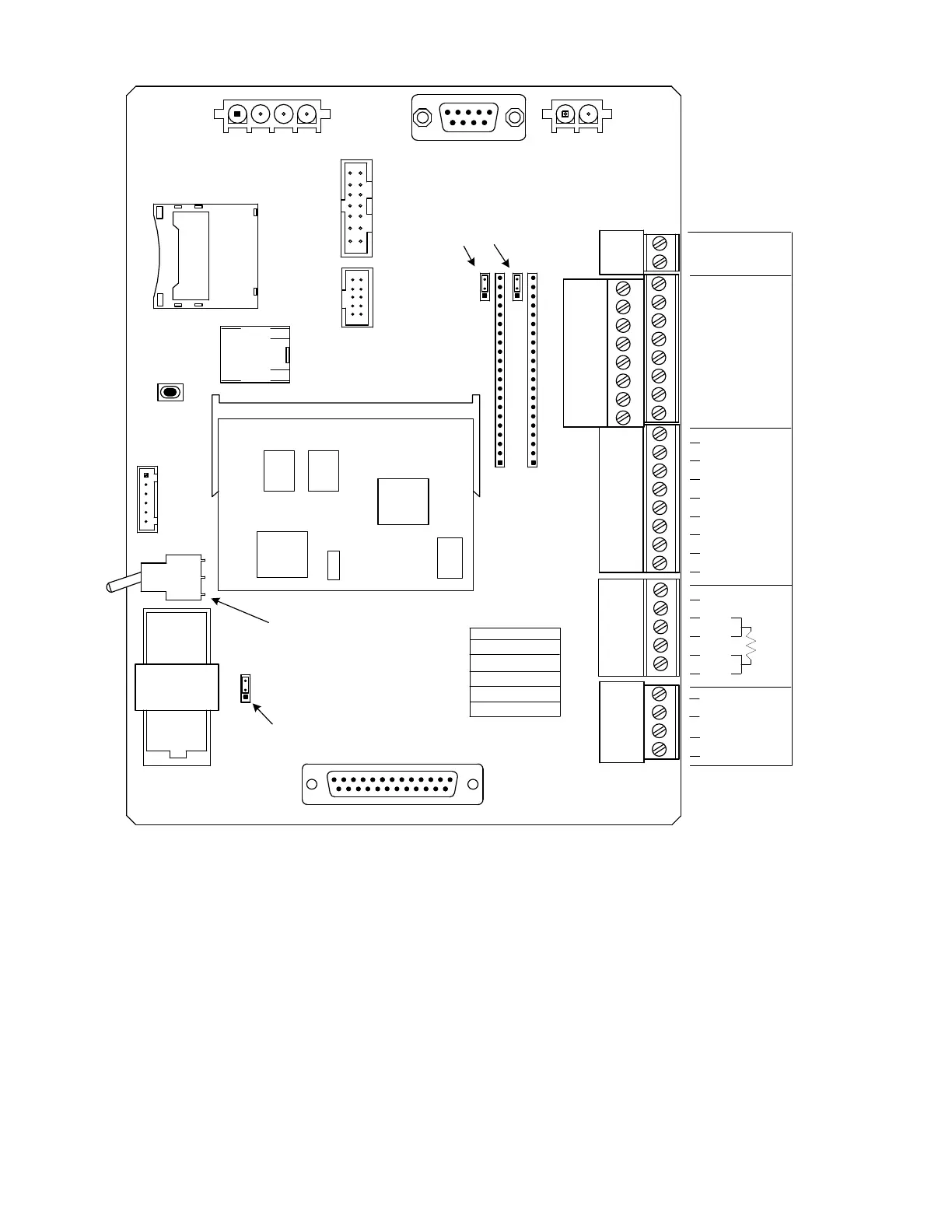
To terminate the RS-485 bus,
jumpers J12 and J11 should be
across pine 1 & 2. The default
position is un-terminated and
jumpers are across pins 2 & 3.
Jumpering across pins 1 & 2 of J1
enables lithium backup of RAM
memory. If lithium backup is
disabled, powering the unit down
will cause a Cold Boot.
If the Security Switch is ON the
proper Security Code must be
entered in PCCU or user will be
unable to connect to XRC
Controller Board and configure
the unit.
1
13
14
25
SD CARD
CPU ENGINE
J9
J6
J7
RESET
XU1
ETHERNET
J2
J18
USB A/B
DISPLAY
S2
COMM2
(-)
(+)
D
AI 1
T
AI 2
(+)
(-)
(+)
(-)
2
1
(-)
IN
DO 2
DO 1
R
(-)
OUT
SHLD
(+)
(-)
(+)
DI/PI 2
GND
DI/PI 1
(+)
(-)
(+)
(-) CHGR
(+) EXT
GND
GND
GND
RTD WIRING
J7-1 DRAIN WIRE
J7-2 WHITE WIRE
J7-3 WHITE WIRE
J7-4 BLACK WIRE
J7-5 BLACK WIRE