50 XFC G4 2103335 Rev AB
4.3 Pipe Mount Installation
If installing directly to the meter run, use the following procedure. Before beginning, review the procedure and the materials
required for installation.
Materials:
— Two U-bolts plus fastening hardware
— Flow computer
mounting brackets
4.3.1 Material Not Supplied
— One pipe saddle
— One 2” x 40” pipe
— Standard 3 or 5 valve manifold or static pressure tap valve
— Stainless steel tubing
Tools needed:
— 5/16” combination wrench or socket with drive.
To pipe mount the flow computer enclosure:
IMPORTANT NOTE: To install the flow computer, it is recommended that two people perform the installation. One
to hold the unit in position and the other to install and tighten the mounting brackets.
The method of installation must be consistent with company policy or contract specifications.
Position the pipe saddle on the meter run. Select a location that allows easy user access and is close to the lines.
Lines should be as short as possible.
Temporarily attach the saddle on the meter run pipe using the U-bolt and associated hardware.
Screw the 2” by 40” mounting pipe into the saddle.
Place a level against the pipe, and vertically align.
Adjust the pipe, mounted in the saddle, until vertical alignment is achieved.
Securely tighten the 2” by 40” pipe in the saddle after vertical alignment, then securely tighten the saddle mounting
bolts.
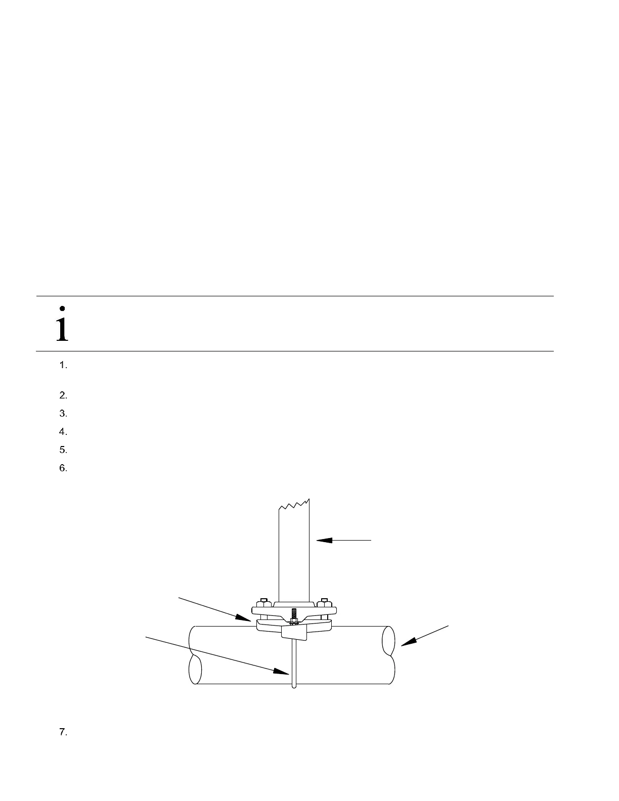
Figure 33 Typical Pipe Saddle Installation
Position the flow computer on the 2” mounting pipe, and secure in place with two U-bolts, flat washers, lock washers
and two 9/16” bolts.
2" x 40"
Mounting Pipe
Meter Run
"U" Mounting
Bolt
Saddle