29 XFC G4 2103335 Rev AB
— Short circuit leakage current: -395 uA typical.
— Input capacitance: 0.1 ufd typical.
— Maximum allowable voltage range on input: -0.5Vdc to 15Vdc.
— Maximum frequency input: 100 KHz @ 50% duty cycle with de-bounce enabled.
— Maximum frequency input: 20 KHz @ 50% duty cycle with de-bounce disabled.
3.6.2.2 Input Specification
— Dry Contact (form A): Open Collector or Active Voltage.
— Minimum contact resistance to activate input: 1000 Ω.
— Voltage threshold to deactivate the input: 3.1 V (referenced to GND terminal.).
— Voltage threshold to activate the input: 0.5 V (referenced to GND terminal.).
— Conductor pairs must be shielded to prevent spurious signals.
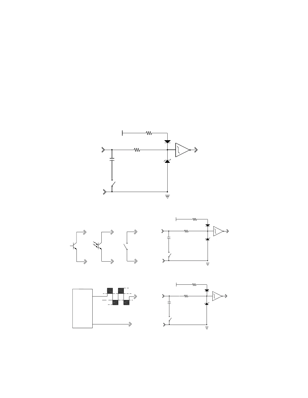
3.6.2.3 Typical Point Schematic
Figure 8 Typical Point Schematic
Figure 9 Example Connections
3.6.3 Digital Output
The Totalflow XFC
G4
provides two digital (12 Vdc) outputs as a means to control external equipment.
GND
SIG
DEBOUNCE SELECT
1K
+5
.1UF
10K
INPUT SENSE
DEBOUNCE SELECT
GND
SIG
.1UF
+5
1K
INPUT SENSE
10K
POINT CONNECTIONS
SIG
GND
OR
SWITCH
GND
OPTO
COUPLER
SIG
GND
NPN
SIG
OR
GND
SIG
DEBOUNCE SELECT
1K
+5
.1UF
10K
INPUT SENSE
GND
TYPICAL VOLTAGE INPUT FIELD
SIG
FIELD DEVICE
COMMON (GND)
SIGNAL
OUTPUT
15 VDC MAX.
-0.5 VDC MIN.
3.1 VDC
0.5 VDC