65 XFC G4 2103335 Rev AB
4.6 Manifold Input Lines
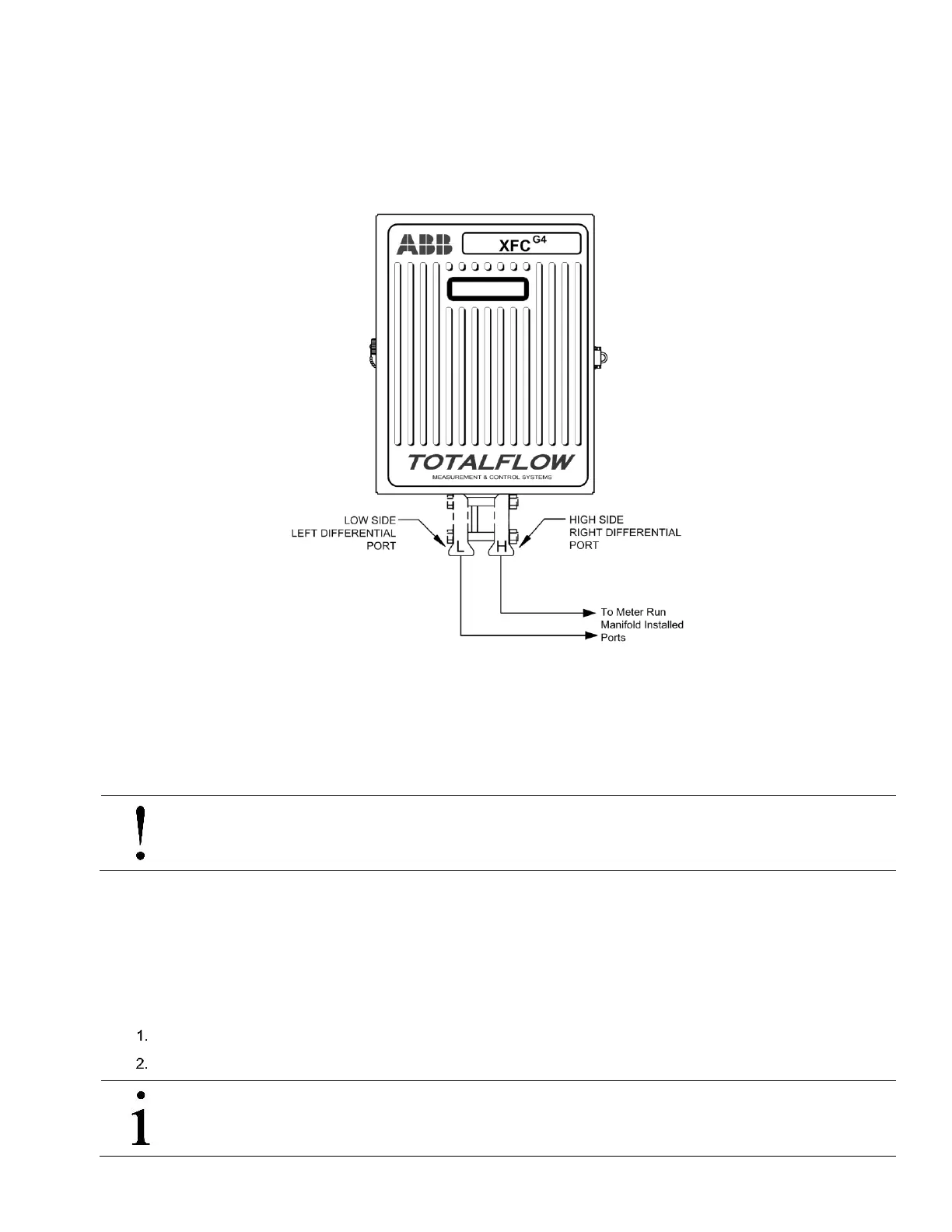
The following procedure will provide the user with the necessary steps to install the manifold. The meter run manifold high (H)
and low (L) pressures terminate in flow computer H and L differential port cells. Differential port cells are located on the bottom
of the flow computer (see Figure 48).
Figure 48 Transducer Low and High Side Ports
Materials (not supplied)
— Stainless steel tubing
— Tubing fittings
NOTICE-Property damage: A backup wrench should always be used when working with stainless steel tubing and
valves. This prevents the fitting from turning or putting tension on the stainless steel tubing.
4.6.1 Step-by-Step Instructions
Tools needed
— Combination wrench x2
— Tubing cutter
To install the manifold input lines:
Install the isolation valves on the meter run (if using 3 or 5 way manifolds).
Install the manifold and tubing to the meter run and the flow computer.
IMPORTANT NOTE: The manifold to the flow computer fittings are not supplied with the flow computer.