74 XFC G4 2103335 Rev AB
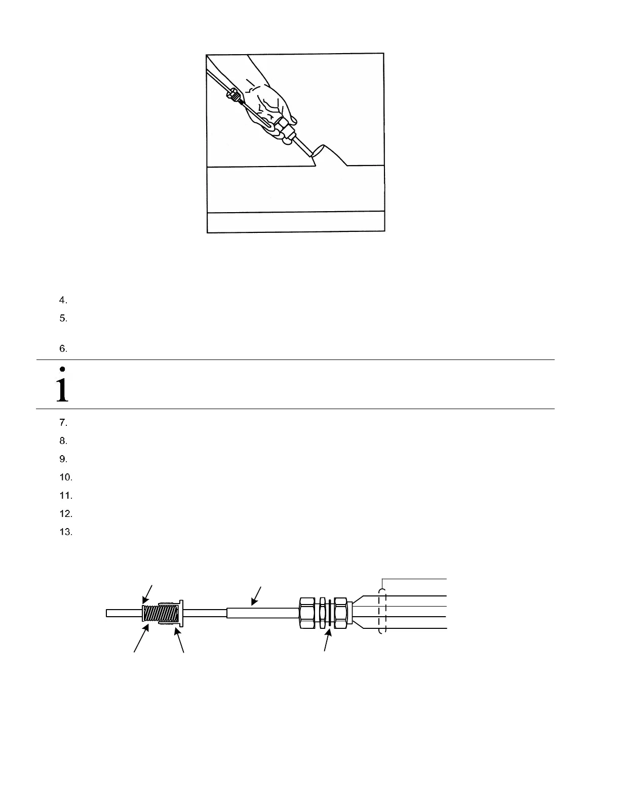
Figure 55 RTD Installation into thermowell
Remove the nut from the water tight cord connector. Leave the nylon sealing ring in place.
Remove the hole plug from the flow computer, and insert the wires through the hole. Allow enough RTD cable to
extend into the flow computer for connecting wires to the RTD termination block, J7.
Secure the RTD probe cable using the supplied sealing ring and nut.
IMPORTANT NOTE: To prevent moisture from entering the flow computer after installing the RTD cord connector,
be certain that the associated connector at the flow computer has a metal backed sealing “O” ring and metal
locking nut attached.
Remove the spade lugs, if attached, from the RTD probe wire.
Trim the wire ends back 1/4”.
Remove the associated terminal block from the flow computer panel (J7).
Loosen the terminal block securing screws.
Insert the wire and then retighten (see Figure 57).
Reinstall the terminal block with the wires attached.
Secure the cable to the meter run pipe with nylon tie wraps. Do not wrap cable around meter run pipe.
The RTD probe is now installed.
Figure 56 RTD Probe Wiring
RTD Probe
WHT
BLK
SHIELD
WHT
BLK
OUT
(-)
(+)
IN
NYLON SEALING RING
BUSHING
RETAINING RING
SPRING