43 XFC G4 2103335 Rev AB
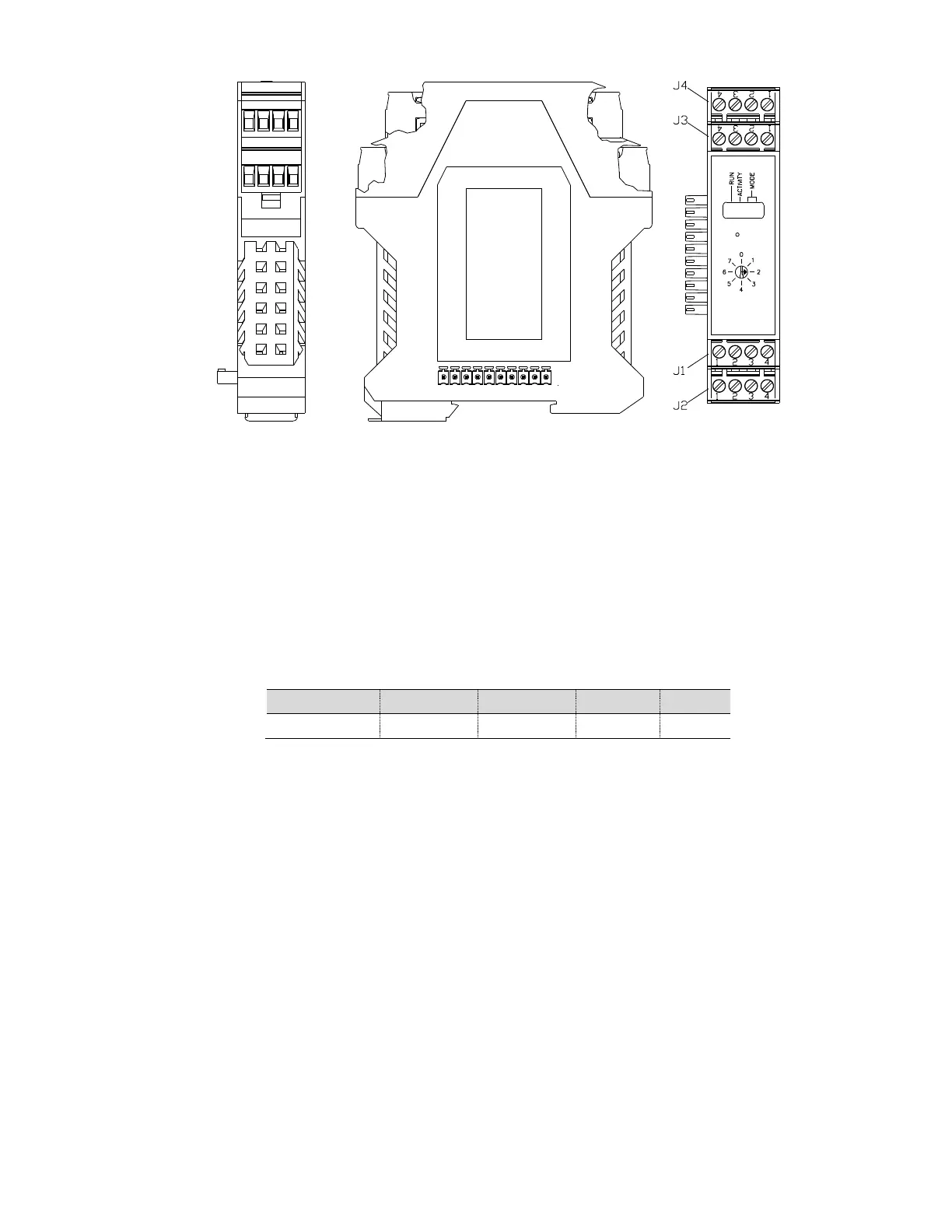
Figure 22 TFIO Module Housing
3.15.1 TFIO Module Specifications
The flow computer 6413 and flow computer 6414 (as shown in Figure 23) systems support up to three modules. For example,
three analog input modules can be connected to the I
2
C bus. Since each module supports eight analog inputs, a total of 24
analog inputs can be added to the I
2
C bus. Each module has the capacity for up to 16 field terminations. For many modules,
eight points are supported, since two terminations are generally required for each point. The flow computer 6713 and flow
computer 6714 (as shown in Figure 24) systems support up to six modules.
Current design criteria dictates that module capacity must also be limited by the panel’s ability to provide power to the modules.
The following table indicates the maximum load capabilites.
Table 7 TFIO Module Loading
All modules are designed to meet Class 1, Division 2, Group C and D Certification.
3.15.2 TFIO Module Hardware
The I/O module hardware is packaged in DIN mount enclosures that employ Phoenix contact technology for field wiring. The
modules also interconnect with each other to provide the necessary power and interface signals along their bus. Installation
consists of snapping the Phoenix connector onto the DIN rail, moving the module into position directly beside the corresponding
module and then snapping it to that module. Likewise, in removing a module, it must first be separated from the module on
either side and then removed from the DIN rail.
All modules have four LED lights, a manual reset button and a selectable address from 0 through 7. On the face plate of each
module is:
— Type of module (name and color coded)
— LED light panel
— Reset button switch
— Module address selector
For additional information, please refer to the TFIO Module User’s Manual.