78 XFC G4 2103335 Rev AB
4.13 XFCG4 Communication, Jumper Settings and Field Wiring
The flow computer main electronic board may require some basic setup and wiring.
The standard flow computer enclosure allows the user access to the main electronic board for configuration of jumpers,
communication modules and switches. All user wiring is wired directly to this board.
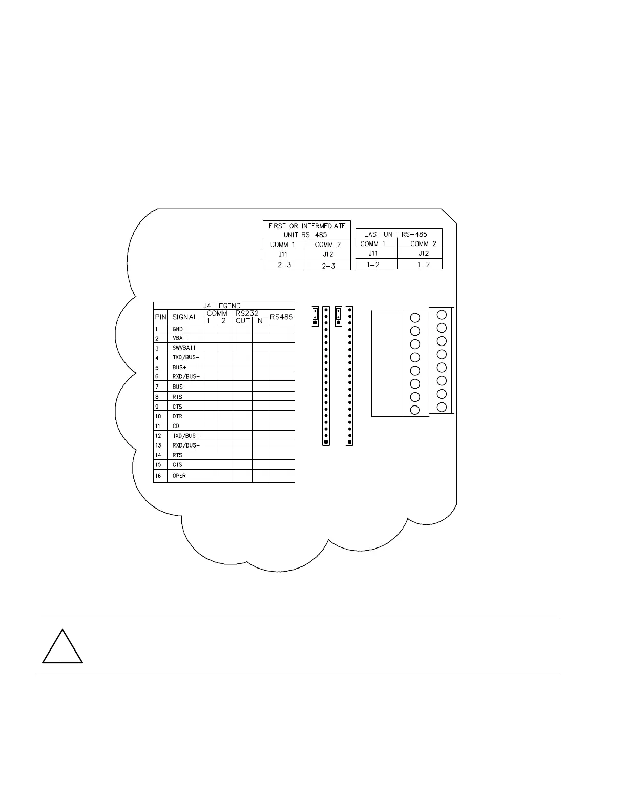
4.13.1 Communication Wiring
You have the ability to program up to two communication ports on the flow computer board. COMM 0 is the local port required
for reading the flow computer with a laptop computer running PCCU32. COMM 1 and COMM 2 can be configured for any
combination of RS 232 or RS 485. For on-board communications wiring inside the standard flow computer enclosure, see Figure
61.
Figure 61 XFC
G4
Standard Communication Wiring
CAUTION- Equipment damage: The flow computer board, as with any electronic board, is susceptible to damage
by static electricity or improper handling. To prevent this from occurring, user should wear a grounding strap.
Remove power to unit prior to changing jumper settings or field wiring to on-board I/O.
4.13.2 Communication Modules
If the flow computer is configured for remote communications, XA1 and/or XA2 will contain a 21 pin communication module
specific to either RS-232, RS-422 or RS-485. If using the RS-485 communication module, J11 and/or J12 jumpers will require
termination on the last or only unit.
1
1
XA1
A
J4
1
J12
3
J11
1
3
COMM 2
COMM 1
B
COMM1
XA2
COMM2
1
4
3
2
5
6
7
8
9
16
15
14
13
12
11
10