158 XFC G4 2103335 Rev AB
IMPORTANT NOTE: If a communication problem still exists and the unit has passed the transceiver check test,
contact Totalflow Technical Support for additional help.
7.4.5 RS-232 Communication Test
The following test procedure is directed from Figure 102: and will assist the user in what may be the possible cause for an
indicated error message.
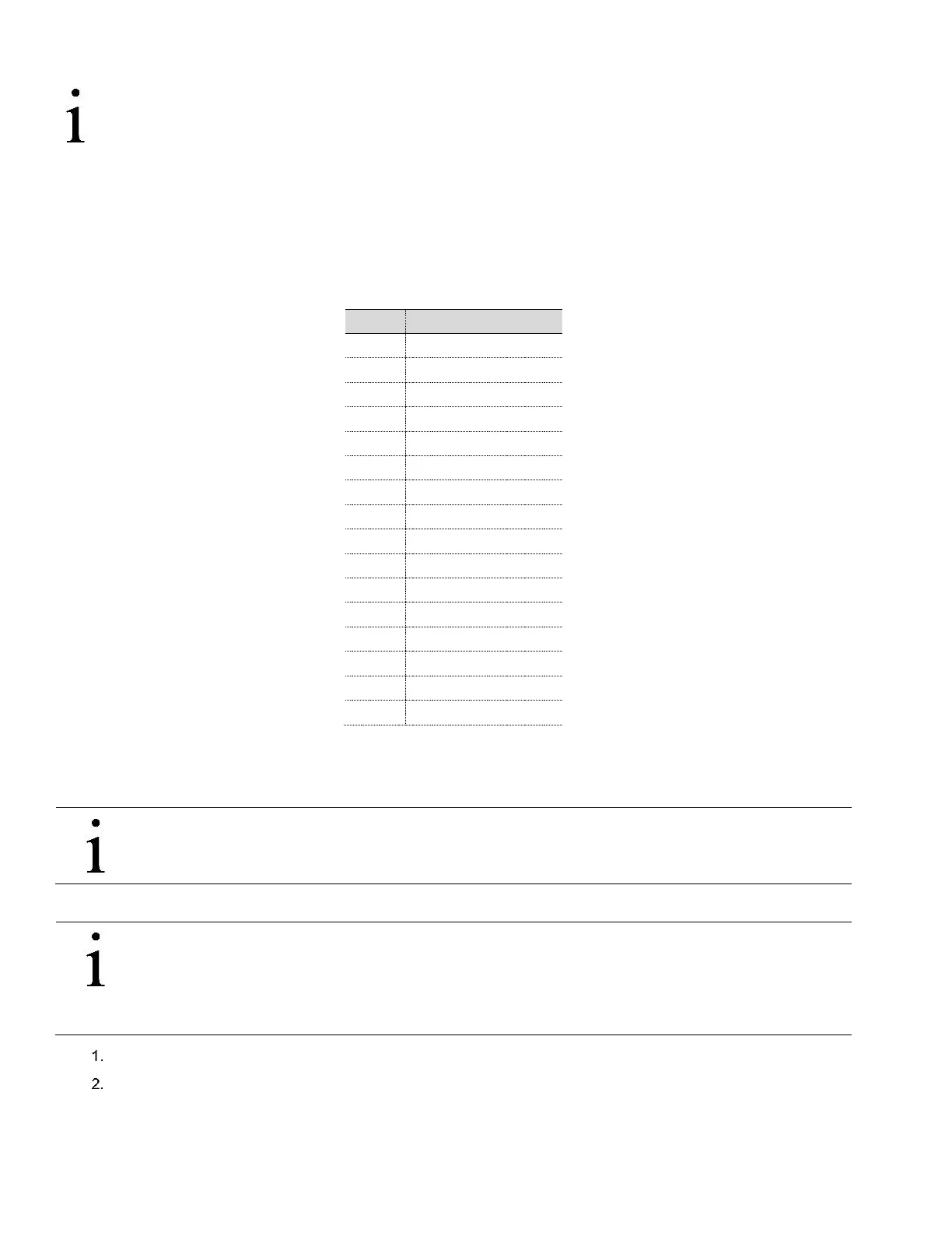
Before performing this test, please verify that the field wiring is correct (Table 19:).
Table 19: RS-232 Field Wiring on XFC
G4
Electronic Board J4 A and B
Tools needed:
— Oscilloscope
IMPORTANT NOTE: When troubleshooting RS-232 mode, verify termination settings of Comm 1-J11 and Comm
2-J12 on XFC
G4
have pins 2 and 3 jumpered.
To perform an RS-232 test:
IMPORTANT NOTE: Voltage on the following steps may be hard to see using a digital multimeter. If available,
an oscilloscope will provide a more accurate reading. To verify, the host software must be continuously polling
the flow computer. Generally speaking, these tests performed on the termination board will only verify incorrect
or damaged wiring. If all previous testing passed, and all wiring, jumper and terminations have been verified
correct, the board will need to be replaced. Contact the office number listed on the back page of this guide.
Open enclosure.
Measure, Using an oscilloscope, receiving data (RXD) voltage on electronic board J4 between:
a. COMM 1, pin 1 (Ground) and COMM 1, pin 6 (Receive Data)
b. COMM 1, pin 1 (Ground) and COMM 2, pin 13 (Receive Data)