32 XFC G4 2103335 Rev AB
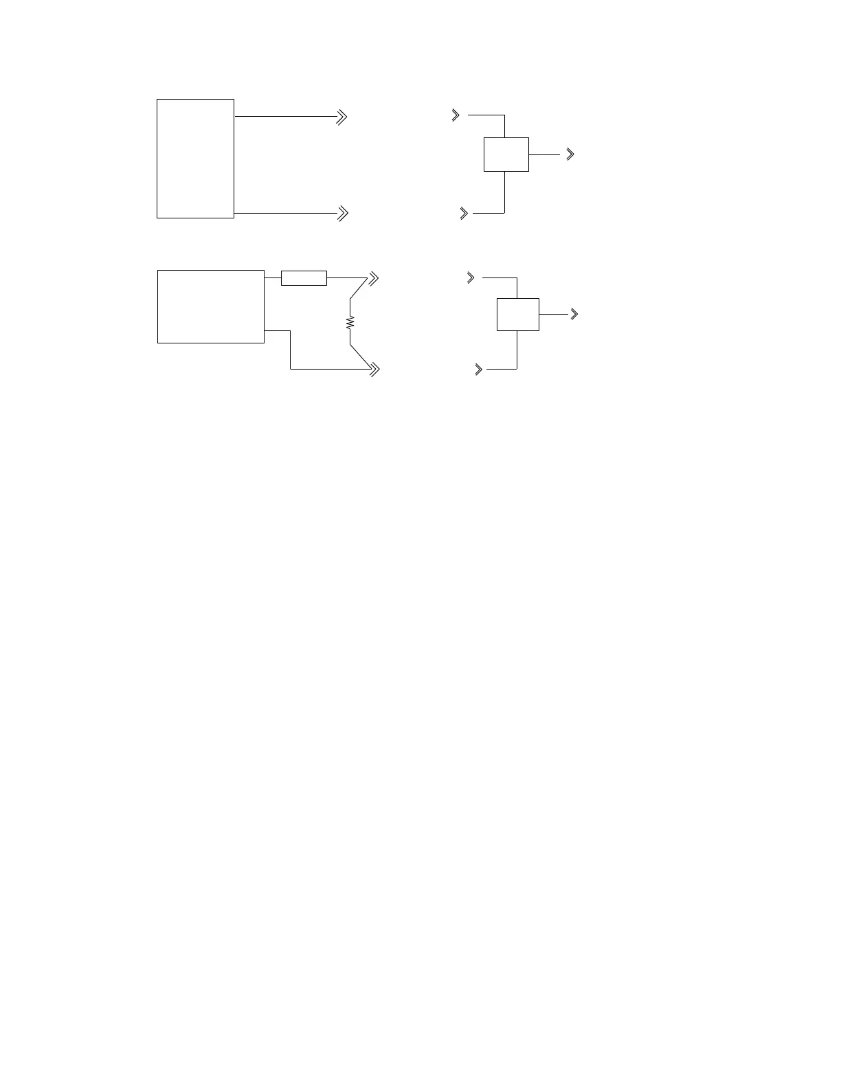
Figure 13 Example Connections
3.7 Functions of the XFCG4
The functions of the flow computer
reflect a design that is practical, straight-forward and efficient. This improved functionality
insures that the flow computer
is easy to use and learn. The flow computer
enables the user to perform the following with a
minimum of effort and greater speed and accuracy.
3.7.1 Records
Complete log period flow and operational records reported (hourly-default) include:
— Average static pressure
— Average differential pressure
— Average flowing temperature
— Corrected volume total
— Corrected energy total
— Operating status and alarms
— Complete daily flow records, including -
— Average static pressure
— Average differential pressure
— Average flowing temperature
— Average extension
— Corrected volume total
— Corrected energy total
— Operating status and alarms
— Complete daily operation statistics, including –
— Percent flowing time
— Percent back flow time
— Percent out of limits (programmable) on SP, DP, Tf and flow rate
— Minimum and maximum values for SP, DP, Tf and flow rate
TYPICAL VOLTAGE ANALOG INPUT FIELD WIRING
SIGNAL
OUTPUT
COMMON (GND)
SIG (+)
GND
FIELD
DEVICE
GND
SIG (+)
Overvoltage
Protection
Network
SIG TO AMU
POWER SOURCE COMMON
OR GND TERMINAL
GND
POWER SOURCE POS. TERM. SIG
TYPICAL 2 WIRE 4--20mA FIELD DEVICE WIRING
(+) XMTR(-)
FIELD DEVICE
GND
SIG (+)
SIG TO AMU
Overvoltage
Protection
Network
250 OHM
USER INSTALLED