121 XFC G4 2103335 Rev AB
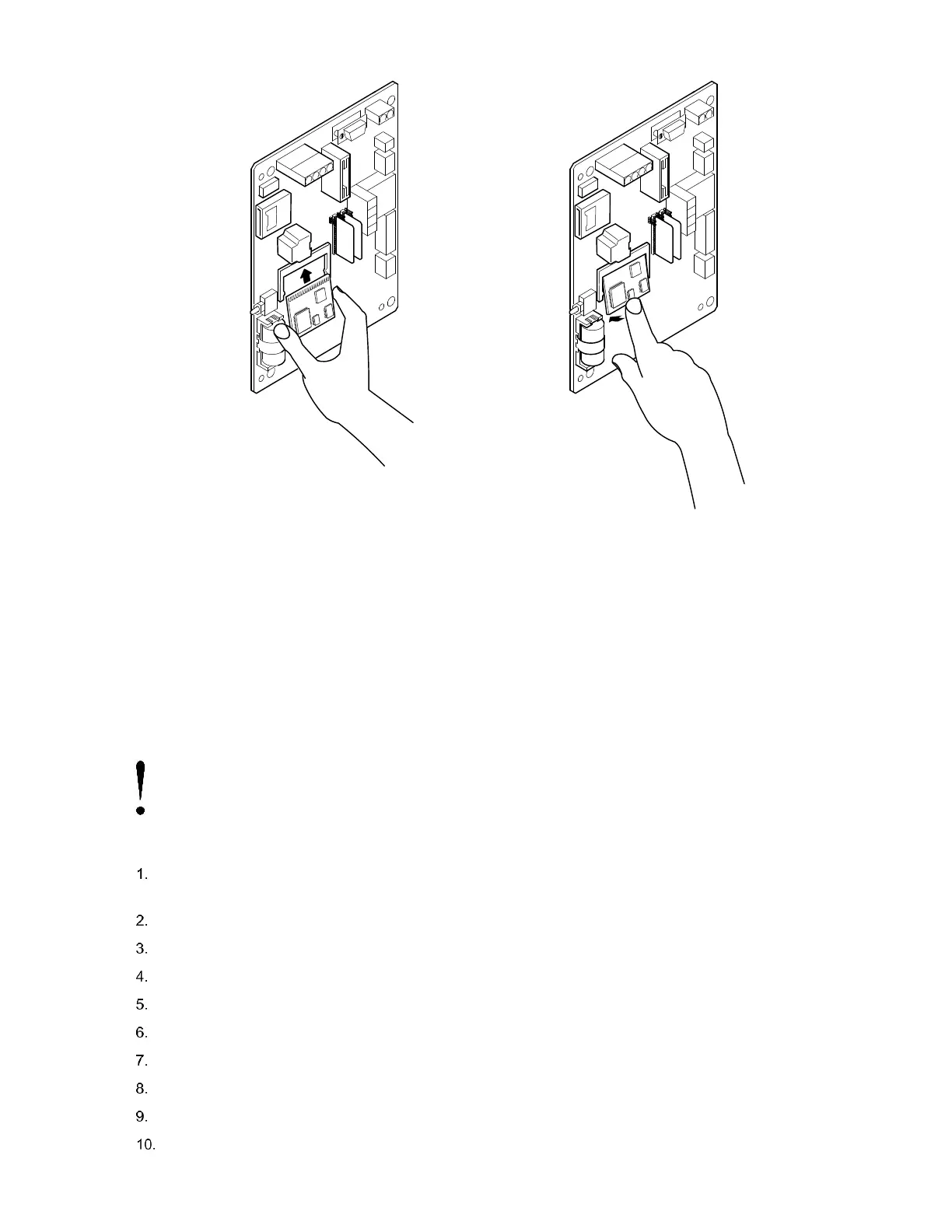
Figure 91: CPU Engine Card Replacement
6.10 Replacing Liquid Crystal Display (LCD) Board
The LCD board is mounted on the backside of hinged doors behind the flow computer board. To access and remove Display
board, perform the following procedures.
Equipment needed:
— Phillips Head Screwdriver
— 3/16” Nut Driver
To replace the Liquid Crystal Display (LCD) board:
NOTICE – Loss of data. Do not remove the board mounted Lithium battery since it provides power to the RAM.
It is recommended that historical flow data be downloaded before accessing and removing LCD board to prevent
potential loss of stored data.
Connect the PC running PCCU32 to the flow computer with either an MMI cable (RS-232), a USB cable or an
Ethernet cable.
Open PCCU.
Collect the Data from the unit as described in section 6.2.1, Data collection (page 108).
Back up configuration files as described in section 6.2.2, Back up configuration files (save) in page 108.
Ensure the J13 (Figure 86) memory backup jumper covers the top two pins.
Verify “LL” battery alarm is not being displayed on the LCD or measure the lithium battery and make sure it is > 3.0V.
Disconnect the battery charger from the terminals EXT CHGR +/- J5 (Figure 86).
Disconnect the Battery Cable from the connector J1 (Figure 86).
Disconnect the LCD port connector J2 (Figure 89).
Disconnect the communication connector(s) J3, J15 or J18 (Figure 89).