31 XFC G4 2103335 Rev AB
Figure 11 Example Connections
3.6.4 Analog Input
The Totalflow XFC
G4
provides two analog inputs as a means of receiving data, represented by continuously varying
voltage/current.
3.6.4.1 Electrical Specification (each point)
— Open circuit voltage: 0 Vdc
— Short circuit leakage current: 0 uA typical
— Input impedance: 21 KΩ typical (0-7.5 V)
— Measurable input voltage range: -0.5 V to 7.5 V
— Maximum voltage on input: 30 Vdc
3.6.4.2 4-20mA Transmitter
If 4-20mA is used for a transmitter on the analog input, see section, Appendix A, page 143. Manufacturer’s specifications can be
extremely misleading. Often, a manufacturer’s specification will claim to operate from 10 to 30Vdc. They are not always clear
that this 10-30Vdc must be applied across the 4-20mA transmitter only (and not across the transmitter/load resistor series
combination).
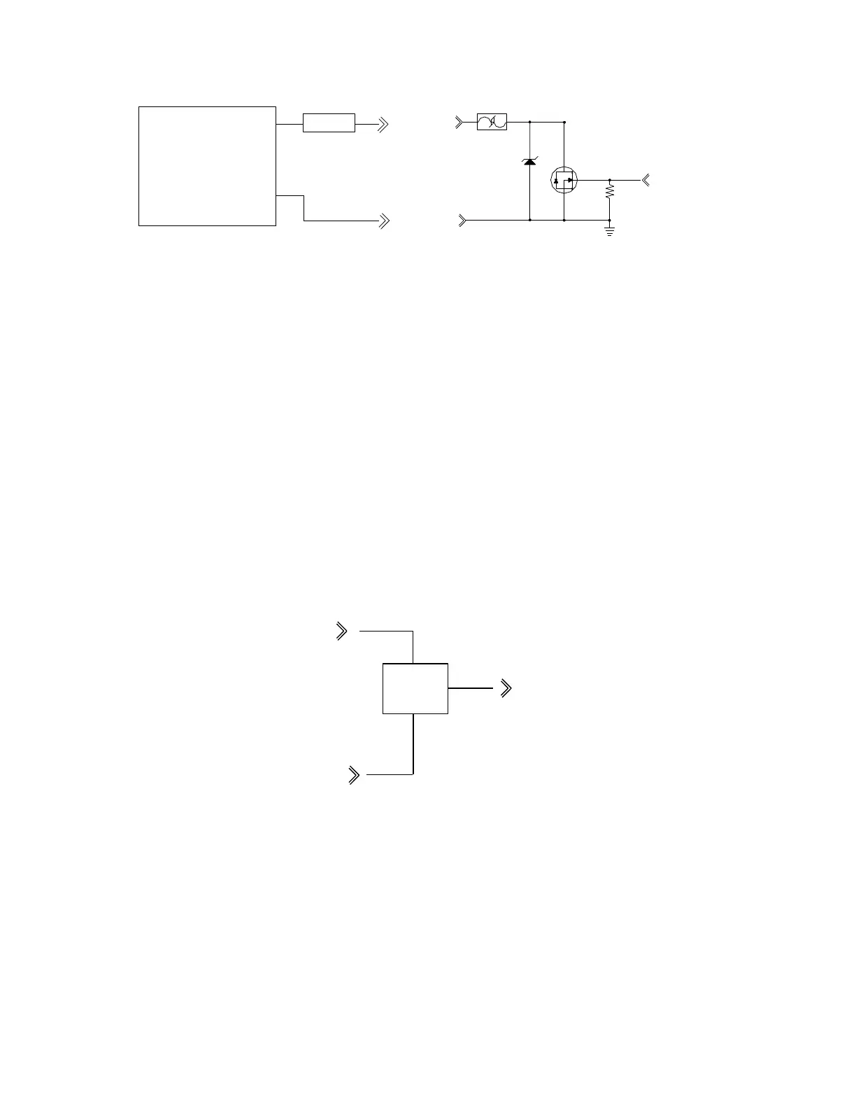
Figure 12 Typical Point Schematic
SIG
GND
24V
2.5A
OUTPUT CONTROL
TYPICAL SINK OUTPUT FIELD WIRING
BATTERY (+) OR POWER
POSITIVE TERMINAL (24 VDC MAX)
SOURCE
BATTERY (-) OR POWER
COMMON OR GND SOURCE
TERMINAL
LOAD
SIG
GND
Overvoltage
Protection
Network
GND
SIG (+)
SIG TO AMU