126 XFC G4 2103335 Rev AB
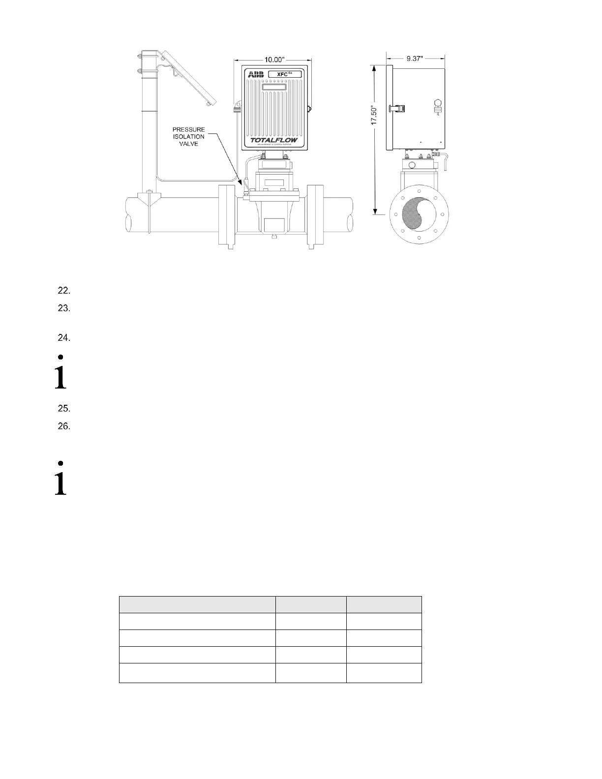
Figure 93: Direct Mount Pulse Meter with Static Pressure Transducer
Access mounting hardware from underside of the flow computer.
Remove eight mounting screws, using a Phillips head screwdriver, washers and lock washers securing static pressure
transducer to the cabinet.
Tilt static pressure transducer slightly upwards then remove unit.
IMPORTANT NOTE: A weather sealing gasket is affixed to top side of static pressure transducer mounting
flange. During reinstallation of transducer, weather sealing gasket must be reinstalled between the transducer
and bottom of the enclosure to keep out moisture and dust.
Perform steps 2 to 15 in reverse order to install replacement static pressure transducer.
Securely tighten the eight mounting screws.
The transducer is now installed.
IMPORTANT NOTE: Before placing static pressure transducer back into operation, the flow computer must be
calibrated as described in section 6.13, Calibration, page 109.
6.13 Calibration
The calibration mode allows the user to calibrate, check and zero the static and differential pressure. In addition, this mode
allows the user to set the (bias) for the resistance temperature detector (RTD). During the initial calibration, the parameters
shown in Table 16: will need to be configured.
Table 16: Calibration Configurable Parameters
Use Fixed Temperature (TF)
6.13.1 Required Test Equipment
The following test equipment is required to calibrate the XFC
G4
XIMV: