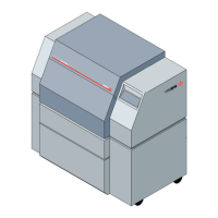
Figure 3.5. The display changes to show that a media supply is loaded.
Left, DualSupply A loaded. Right, DualSupply B loaded.
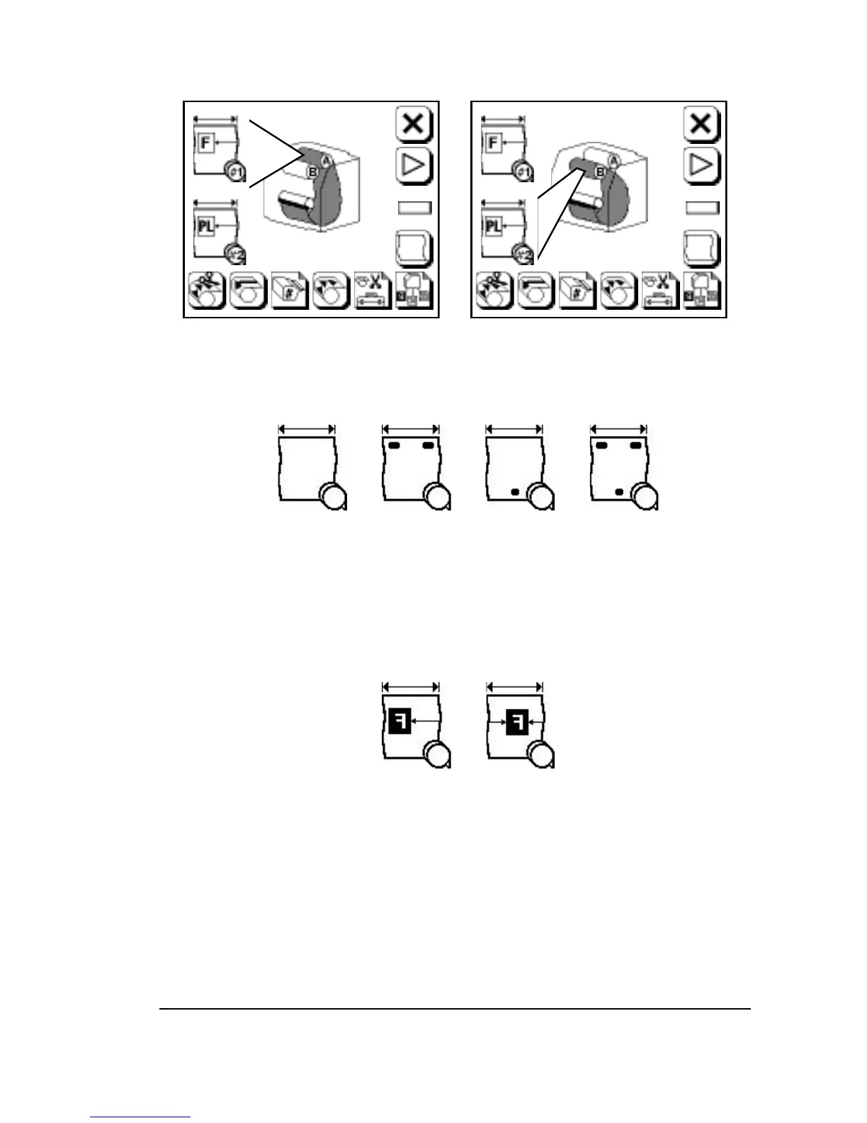
Figure 3.6. Punch modes. Adjust in Cassette Screen.
These symbols are used as a convention to represent the many different
punch configurations that are available.
➀
—Punches off.
➁
—Top punches on.
➂
—Bottom punches on.
➃
—Top and bottom punches on.
Figure 3.7. Alignment mode. Adjust in Configuration Screen.
➀
—Flush left.
➁
—Centered.
➀ ➁ ➂ ➃
➀ ➁
Using the Control Panel
•
3–9