138 Agilent Restricted Agilent 5110/5100 ICP-OES Service Manual
4 Removal/ Installation, Replacement and Adjustment
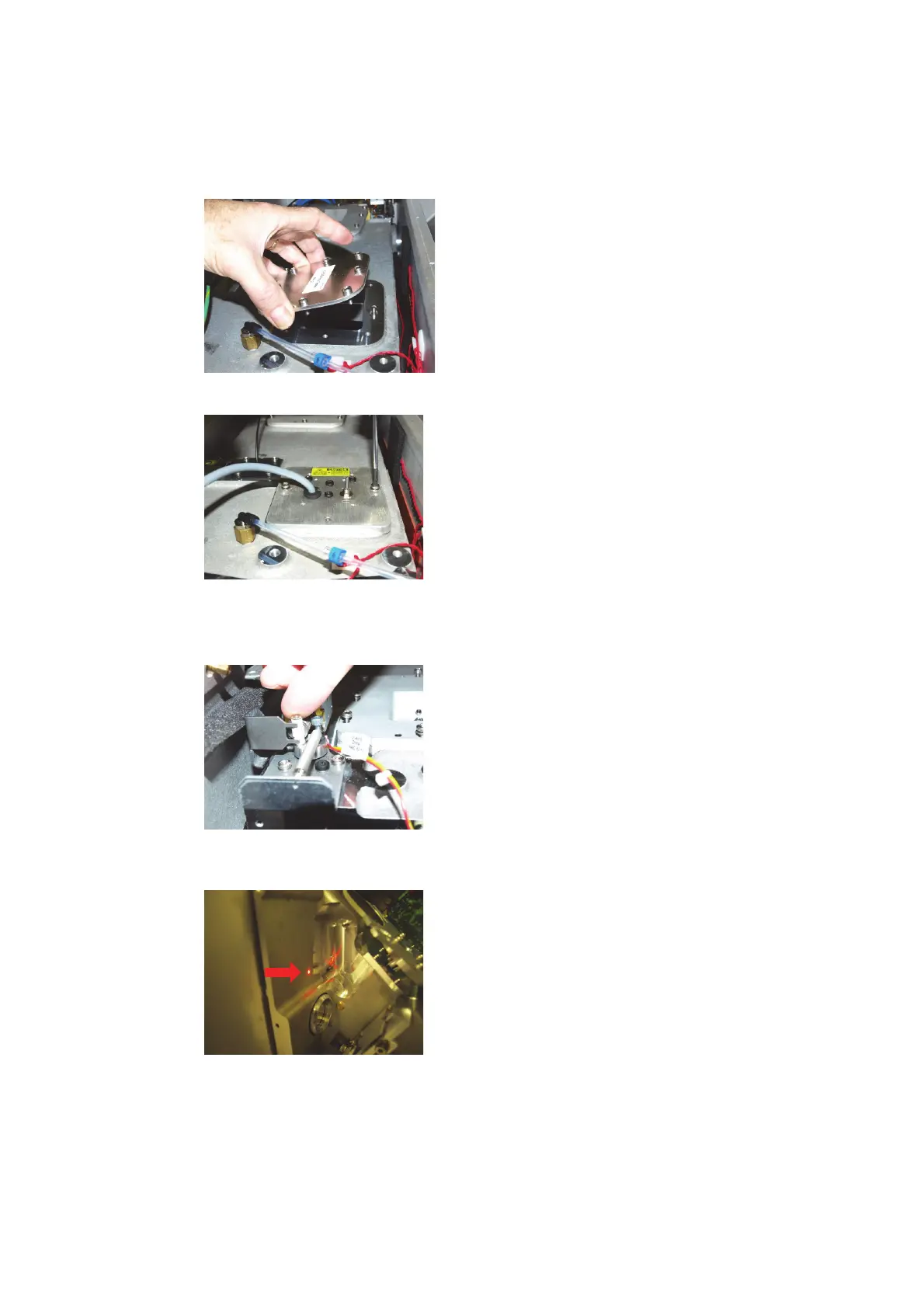
Optical alignment
1 Remove the instrument slit and replace with alignment slit. Secure in position with at least
the top screw. (See section on Entrance slit for removal process).
2 Remove laser jig access cover.
3 Install the laser back lighting fixture, secure with 2 screws and connect to a 5 volt power
supply.
4 Turn-on the laser back lighting fixture.
5 Manually open the shutter solenoid by pushing solenoid actuator to the right of the
instrument (or use instrument “detector” diagnostics page to open solenoid shutter).
6 Remove radial mirror M2 and ensure the laser image aligns into the alignment hole in the pre
optics casting. If misaligned, slight adjustment of pilot mirror screws (vertical and horizontal)
may be required to centre the image. Replace Mirror M2.
7 Interrupt the light path with the mirror beam combiner (Axial position).

 Loading...


