Agilent 5110/5100 ICP-OES Service Manual Agilent Restricted 31
3 General Information
Power distribution
Power distribution
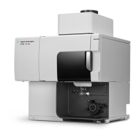
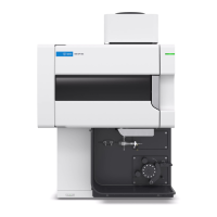
The Agilent 5110 ICP-OES instrument is powered via a single phase 20 Amp IEC inlet socket.
Operating input voltage is 200-240VAC at 15 Amps maximum (2.9 kVA total maximum power
consumption) with nominal running power consumption of 2.2kVA.
Instrument electronics is powered by a 24Volt 320W switching power supply which forms part
of the mains power module. The mains power module communicates with the control
electronics via a high speed (1 Mbps) Serial Line Interface Protocol (SLIP) bus. The mains power
module also controls the following circuits:
• Interlock protected power to the RF power supply
• Cooling fan
• Polychromator heating
• Pre optics thermal stabilizer
The module also houses a standby circuit that activates main power to the instrument when the
instrument power switch on the front panel is depressed.
24 volt power is fed from the mains module to the control board where it is distributed primarily
via the Serial line Interface Protocol (SLIP) bus system to power the various sub system
modules. The sub system modules regulate the 24V down to appropriate voltages for control.
The Gas Control module, Advanced Valve System and the Peristaltic Pump module have a
separate 24V supply line due to higher current drain.
The RF system is powered by a separate DC RF power supply producing 0-200VDC at 11 Amps
into the Solid State RF (SSRF) oscillator. The SSRF oscillator is a free running 27MhZ oscillator
generating an adjustable power output range of 0.7kW-1.5kW. The RF system is interlocked to
ensure start up only occurs with all safety and control systems satisfied.
 Loading...
