Agilent 5110/5100 ICP-OES Service Manual Agilent Restricted 95
4 Removal/ Installation, Replacement and Adjustment
RF Current Sensor
26 Go to the Plasma diagnostics page, Sequence tab.
27 Click on “Read from RAM” to load current settings.
28 Check the Value of “Ig_PS_I” and change to 3.5 if it is any other number.
29 Click on “Send to RAM”.
30 Click on “Write RAM to EEPROM” to complete the process.
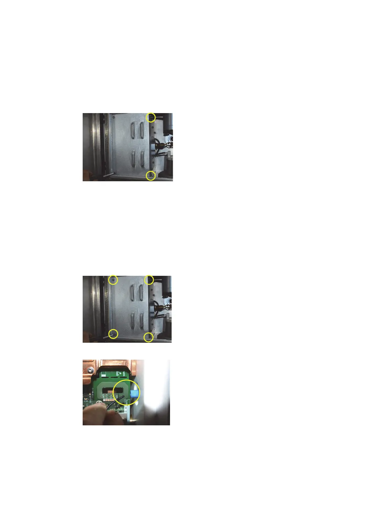
31 Assemble cover and 4 screws. Tighten screws circled first before tightening remaining 2
screws to ensure the cover fits correctly.
RF Current Sensor
The RF Current Sensor is a diagnostic aid only and isn’t required for a Plasma to be sustained.
The current sensor outputs the Work Coil current and the value can be seen in the RF Generator
Test. If there is a problem with the Plasma lighting it will not be as a result of the current sensor.
1 Remove 4 torx 20 screws and remove SSRF Cover.
2 Loosen thimble and remove optical fibre from assembly.
3 Remove blue thimble to allow sensor to pull through from the other side.

 Loading...


