98 Agilent Restricted Agilent 5110/5100 ICP-OES Service Manual
4 Removal/ Installation, Replacement and Adjustment
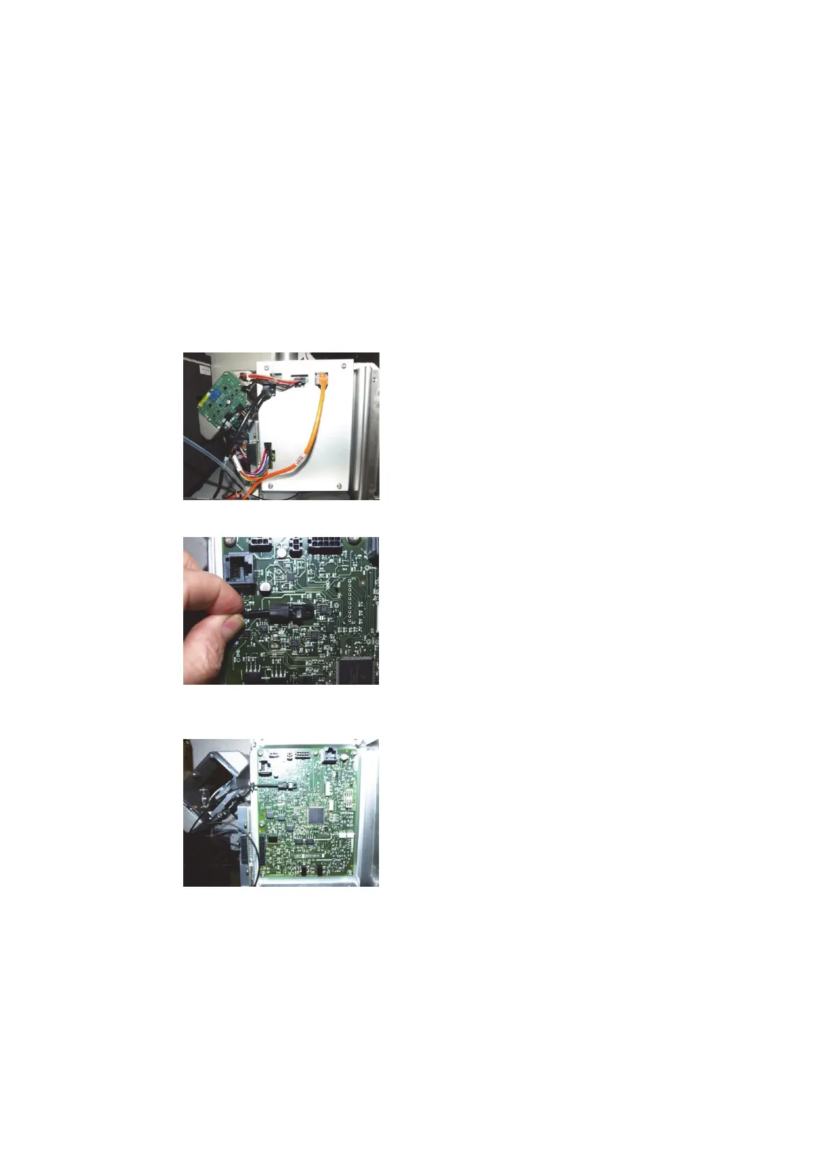
SSRF Control board
SSRF Control board
The SSRF control board regulates RF Power to the Coil via the SSRF filters and RF Oscillator and
communicates with instrument control via an RS485 SLIP bus.
The board includes a Pulse Width Modulator (PWM) drive control for the RF Oscillator (FET bias)
with feedback circuits for current and voltage control. Interlock monitoring circuits include
plasma sense, RF box temperature, water flow and air flow with RF cutout interlock for fail
condition. The igniter is also triggered from the SSRF control board.
The SSRF Control board is attached to the left hand side of the RF box and is accessible with the
removal of the left hand side cover and left hand top cover.
1 Remove 4 torx 20 screws and remove cover.
2 Loosen current sense fibre optic connector by rotating anticlockwise and slide the fibre from
the receptacle.
3 Remove 6 torx 20 screws, disconnect cables and remove board.
RF Power Supply (RFPS)
The RF power supply is an OEM module that supplies +/- 100VDC to the Solid State RF
oscillator. There are no user serviceable parts within the module.

 Loading...


