140 Agilent Restricted Agilent 5110/5100 ICP-OES Service Manual
4 Removal/ Installation, Replacement and Adjustment
Optical alignment
Camera image location adjustments
Location adjustment aligns the polychromator focus plane with the instrument camera
assembly. Focus mirror DLA and wavelength adjustment screws are set to position the
dispersed orders and wavelengths to correspond with the theoretical pixel positions on the
camera assembly.
The location adjustments are made using a simple spectra produced by the plasma.
Characteristic argon peaks are identified and properly positioned on the camera and then the
focus mirror is adjusted by properly positioning a zinc peak.
In the case of severe misalignment of the focus mirror, the optical image may not fall on any of
the camera pixels. If the image is not displayed on the location page the following corrective
actions should be taken.
1 Check that the shutter assembly is in the open position when reading.
2 Set the backing plate of the focus mirror square to the polychromator casting by a distance
of about 5mm using a 5mm hex key as a spacer.
3 Return to the optics page of diagnostics. Use the full illumination LED and the diagnostics
graph function to verify correct camera assembly operation.
4 Ignite the plasma and aspirate blank solution.
5 Remove the polychromator access cover from the left side of the instrument.
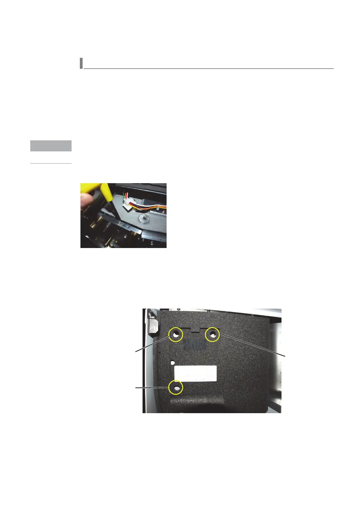
Figure 15. M7 Focus mirror adjustments
6 Access the mirror adjustment screws by lowering the insulation flap on the polychromator
outer box insulation.
7 Go to the Location page of the Polychromator alignment software.
8 On the location page under Intensity Map tick Ar.
Focus Adjustment
Screw
Wavelength Adjustment
Screw
DLA Adjustment
Screw

 Loading...


