Agilent 5110/5100 ICP-OES Service Manual Agilent Restricted 141
4 Removal/ Installation, Replacement and Adjustment
Optical alignment
9 Under Defaults set INT to 30 msec and pixel spread to 55 pixels.
10 Under Echelle tick Active, Left side, Right side.
11 Press Read.
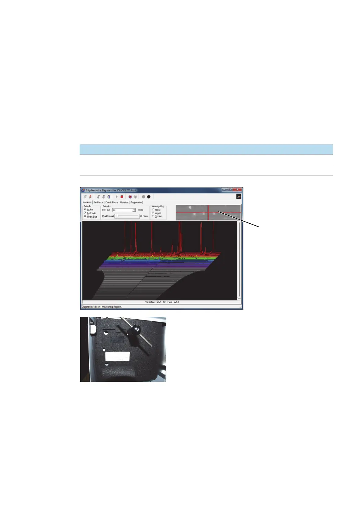
There are seven major peaks in the simple spectra that are used to begin a location adjustment.
The major peaks are emitted by oxygen and argon in the plasma and should occupy DLAs 19
through 22.
The focus mirror should be adjusted so that the left side of the location screen displays the 4
major peaks and the right side of the location screen displays the remaining 3 major peaks -see
below.
12 Turn the DLA adjustment screw to position the major peaks on the correct DLAs. Adjust
Counter clockwise if peaks are below the red line.
Adjustment screw Direction Image movement
DLA Clockwise Increase DLA number
Wavelength Clockwise Decrease pixel number
Peaks to be on the red line

 Loading...


