Agilent 5110/5100 ICP-OES Service Manual Agilent Restricted 143
4 Removal/ Installation, Replacement and Adjustment
Optical alignment
Location adjustments should be complete before attempting focus adjustments.
The focus alignment of the polychromator and camera assembly is based on the Zn 213.856
nm emission line. The half-height full width resolution at this wavelength should routinely be
less than 8.5 pm.
1 Remove the polychromator access cover from the left side of the instrument.
2 Access the focus mirror adjustment screws by lowering the insulation flap on the
polychromator outer box insulation.
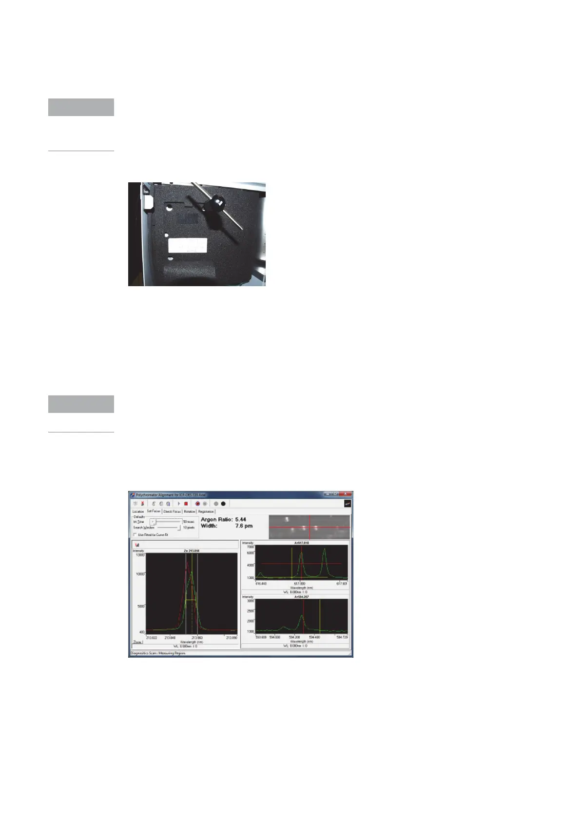
3 Go to the Set Focus page in the polychromator alignment software folder.
4 Ignite the plasma (if required) and aspirate wavelength calibration solution.
5 Under Defaults set INT to 50 msec.
6 Open Shutter and Press Read.
The intensity map will display the positions of argon 617.310nm, 617.018nm and 592.868nm
peaks. While adjusting the focus mirror always position Argon 617.310nm and 617.018nm on
the horizontal axis (red line) centered around the vertical axis (red line).
7 Using the wavelength adjustment screw position Zn 213,856 at DLA69 pixel 421, marked by
the short yellow vertical dotted line in the Intensity window.
8 Using the DLA screw maximize the Zn 213.856 nm peak for the highest intensity.
9 Record the half height full width of the Zn peak as indicated in the width field at the top of the
window.
10 Adjust the focus adjustment screw clockwise ¼ of a turn.
11 Adjust the wavelength adjustment screw clockwise ¼ of a turn.
12 Adjust the DLA adjustment screw clockwise ¼ of a turn.

 Loading...


