42 Agilent Restricted Agilent 5110/5100 ICP-OES Service Manual
3 General Information
Plasma RF
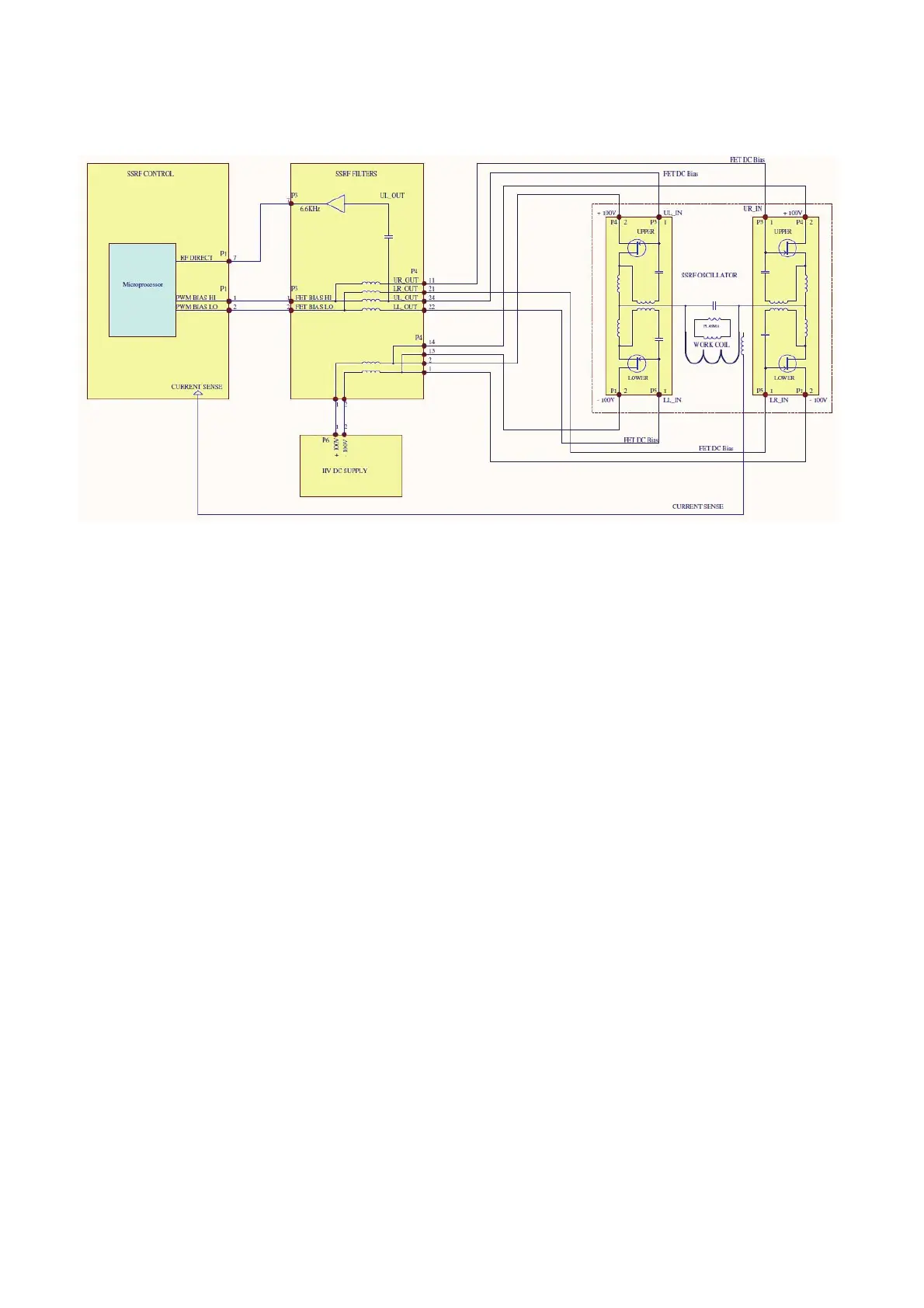
Figure 3. SSRF Generator and control circuits block diagram
The RF power levels are set through a combination of varying the DC supply voltage from the RF
power supply (RFPS) and adjusting the FET DC bias voltage using PWM from the SSRF control
processor. Varying the FET bias voltage compensates for changing oscillator frequency as
circuit impedance changes with changes in plasma chemistry. See above for simplified block
diagram of RF system, (oscillator, power supply and control circuits).
Monitoring circuits include plasma sense, RF box temperature, water flow and air flow with RF
cutout interlock for a fail condition. The igniter is triggered from the SSRF filter board.

 Loading...


