Pseudowire Switching
Page 176 7705 SAR OS Services Guide
To enable pseudowire redundancy, the first pseudowire segment must be a static pseudowire
(that is, TLDP disabled). The second pseudowire segment can then be configured with up to
four redundant spoke SDPs. See Pseudowire Redundancy on page 190 for instructions on
configuring redundancy. Pseudowire switching with pseudowire redundancy also supports
standby signaling. See Active/Standby Mode for Pseudowire Redundancy (Standby
Signaling) on page 195 for more information.
Pseudowire Switching Behavior
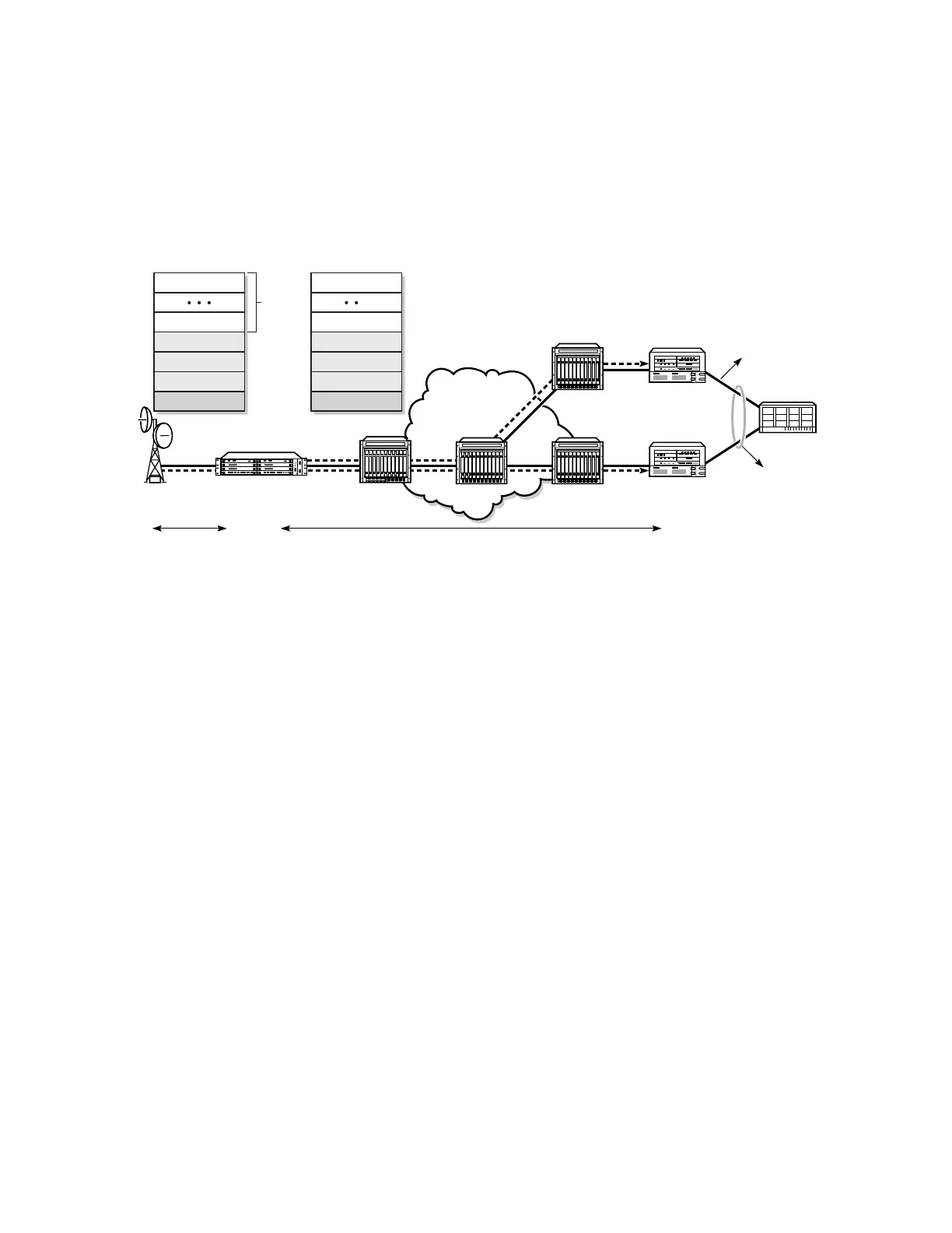
In the network in Figure 31, T-PE nodes act as masters and pseudowire switching nodes
(S-PE nodes) act as slaves for the purpose of pseudowire signaling. Switching nodes need to
pass the SAP interface parameters of each PE to the other PE. T-PE1 sends a label mapping
message for the Layer 2 FEC to the peer pseudowire switching node; for example, S-PE1. It
includes the SAP interface parameters, such as MTU, in the label mapping message. S-PE1
checks the FEC against the local information, and if a match exists, it appends the optional
pseudowire switching point TLV to the FEC TLV in which it records its system address.
Figure 30: Simplex to Redundant Pseudowire Switching
Metro Ethernet
NW
20773
7705 SAR
MEN
BSC
7750 SR
T-PE2
Node B
MEN
MEN
7750 SR
T-PE1
MEP 1
STM-1
AT M
MC-APS
PW segment 1
IP Encapsulation
PW segment 2
MPLS Encapsulation
S-PE
ATM Cell #1
ATM Cell #N
Optional CW-1
PW Header-1
IP
Ethernet
ATM Cell #1
ATM Cell #N
Optional CW-2
PW Header-2
MPLS
Ethernet
no
change