8 Intellex
®
LT Digital Video Management System
Rear Panel
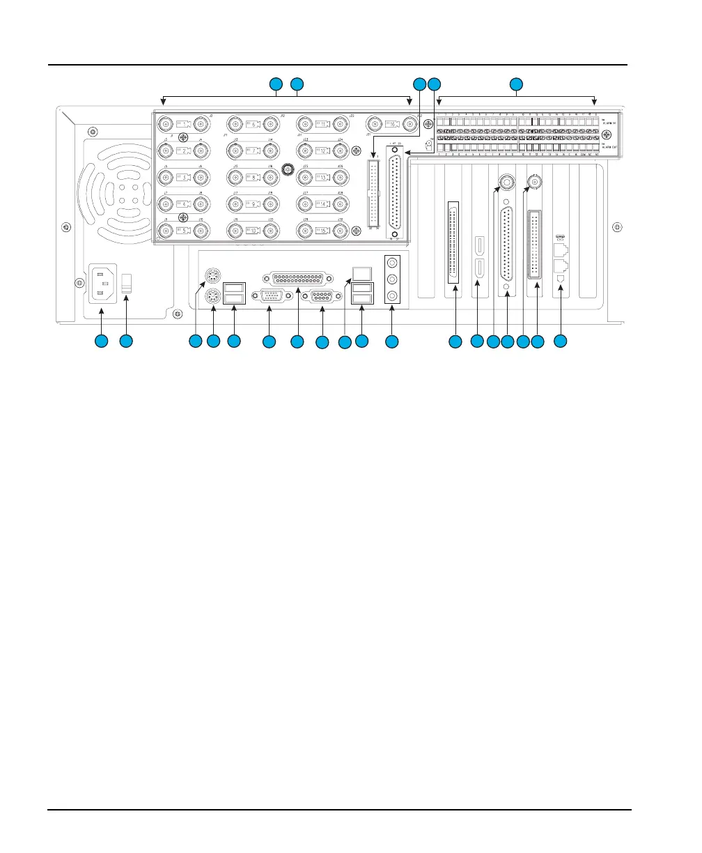
Figure 4 — Rear Panel Connectors
REAR PANEL
1. Camera In — The left of each pair of BNC connectors inputs
video. The connectors accept the composite video output of
color or B&W cameras.
2. Camera Out — The right of each pair of BNC connectors
provides passive loop through camera video from the
corresponding camera input. Camera termination is
configured in the Cameras portion of the Setup Options
screen. Therefore, physical terminators are neither installed
nor required.
3. External Cable Connector — An external cable connects
this IDC34 male header connector to #21 below.
4. External Cable Connector — An external cable connects
this DB37-P female connector to #19 below.
5. Alarms — These connectors accept up to 16 alarm inputs
and 16 alarm outputs.
6. Power In — This connector accepts any AC main power cord
with an IEC-320-C13 plug. (Most standard computer cords
meet this requirement.)
CAUTION: Before connecting power, set the voltage switch
to the correct voltage (“115” or “230”).
&
1
2
3
6 7 9
8
10 10
11
12 16
17
14
18 19 21
4 5
22
2015
13