EControl/Status Registers
E – 3
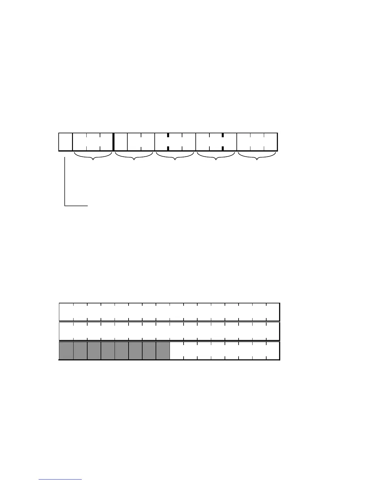
Default bit values at reset are shown; if no value is shown, the bit is undefined at reset.
Reserved bits are shown on a gray field—these bits should always be written with zeros.
Memory-Mapped Registers
1514131211109876543210
DWAIT0
or
DWAIT1
or
DWAIT2
or
DWAIT3
or
DWAIT4
or
0 111111111111111
IOWAIT0
(ADSP-2181)
IOWAIT1
(ADSP-2181)
IOWAIT2
(ADSP-2181)
IOWAIT3
(ADSP-2181)
DWAIT
(ADSP-2181)
ROM Enable
(ADSP-2172, ADSP-21msp59)
1 = enable
0 = disable
Waitstate Control Register
DM(0x3FFE)
1514131211109876543210
TPERIOD Period Register
TCOUNT Counter Register
TSCALE Scaling Register
00000000
Timer Registers
DM(0x3FFC)
DM(0x3FFB)
DM(0x3FFD)

 Loading...

