Section 1 General
1-8
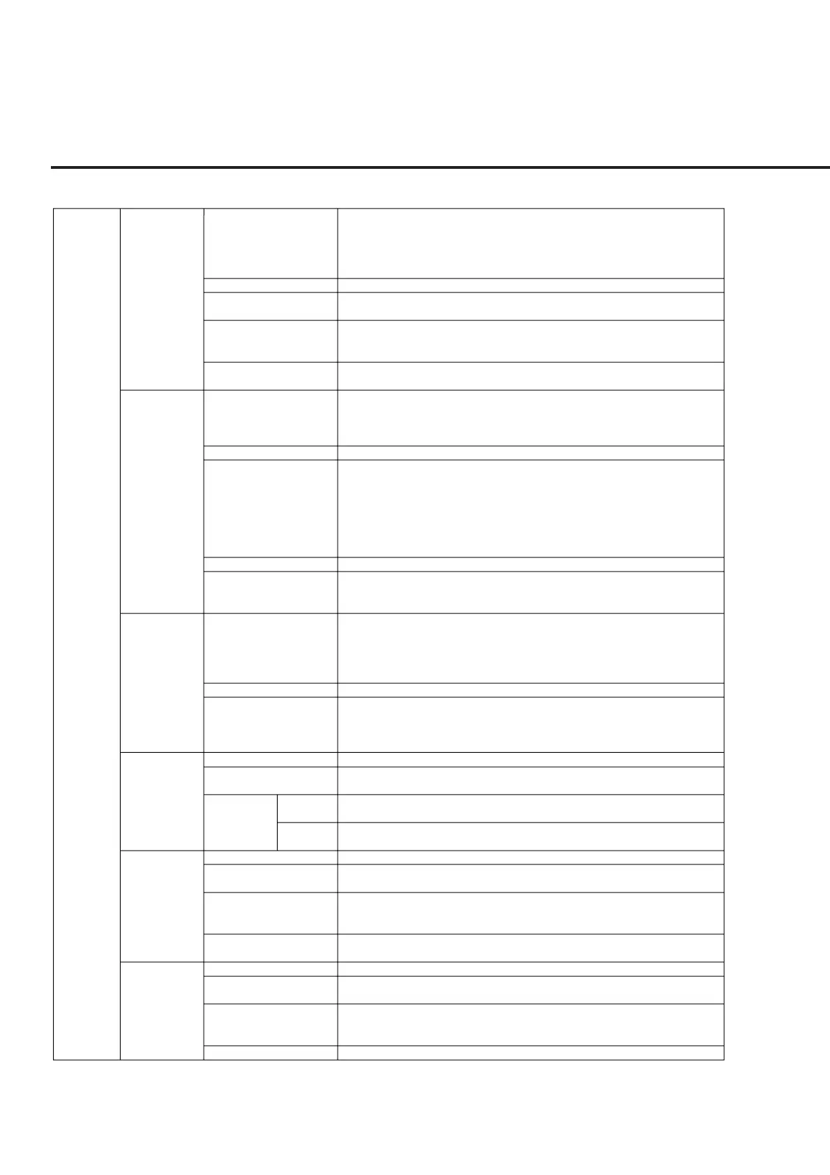
Table 1-7 MT8801C Option 12 : CDMA Measurement Specifications
Transmission
measurement
Frequency range
Level range
Frequency
measurement
Waveform quality
Residual vector error
Frequency range
Measurement range
Measurement accuracy
Input connector
Measurement item
Frequency range
Level range
Measurement accuracy
Frequency range
Input level range
Standard
Measurement mode
method High speed
mode
Frequency range
Input level range
Measurement method
Measurement range
Frequency range
Input level range
Measurement method
Measurement range
824.01 MHz to 848.97 MHz, 30 kHz step (IS-95A, TSB74)
1850.00 MHz to 1909.95 MHz, 50 kHz step (J-STD-008)
887.0125 MHz to 888.9875 MHz, 898.0125 MHz to 900.9875 MHz,
915.0125 MHz to 924.9875 MHz, 12.5 kHz step (ARIB STD-T53)
1715.05 MHz to 1780.00 MHz, 50kHz step (KOREA-PCS)
+40 to –20 dBm (average power in burst, Main connector)
Measurement error: Reference ±10 Hz
Guaranteed after Adjust Range
Measurement range: 0.9 to 1.0
Measurement error: ±0.003
Guaranteed after Adjust Range
<5%
Guaranteed after Adjust Range
824.01 MHz to 848.97 MHz, 30 kHz step (IS-95A, TSB74)
1850.00 MHz to 1909.95 MHz, 50 kHz step (J-STD-008)
887.0125 MHz to 888.9875 MHz, 898.0125 MHz to 900.9875 MHz,
915.0125 MHz to 924.9875 MHz, 12.5 kHz step (ARIB STD-T53)
+40 to –50 dBm
±0.4 dB (+40 to 0 dBm, after Power Meter calibration)
±0.4 dB (+40 to –10 dBm, after Power Meter calibration, 18 to 28°C)
±0.7 dB (+40 to –10 dBm, after Int. OSC. Calibration, 18 to 28°C)
Linearity: (Reference level –10 dBm)
0 to –10 dB; ±0.1 dB
–10 to –20 dB; ±0.2 dB
–20 to –40 dB; ±0.5 dB
Main connector
Modulation analysis, gated output power measurement, power meter, standby output
power measurement, access probe output power measurement, open loop power
control time response measurement
824.01 MHz to 848.97 MHz, 30 kHz step (IS-95A, TSB74)
1850.00 MHz to 1909.95 MHz, 50 kHz step (J-STD-008)
887.0125 MHz to 888.9875 MHz, 898.0125 MHz to 900.9875 MHz,
915.0125 MHz to 924.9875 MHz, 12.5 step (ARIB STD-T53)
1715.05 MHz to 1780.00MHz, 50kHz step (KOREA-PCS)
+40 to –10 dBm (Main connector)
±10% (0°C to 50°C, 0 to +40 dBm)
±10% (+40 to –10 dBm, average power)
Input connector: Main connector
Guaranteed after zero-point calibration, and at ≤–53 dBm signal generator output level
20 MHz to 2.2 GHz
0 to +40 dBm (average power in burst) at MAIN connector
–20 to +20 dBm (average power in burst) at AUX connector
Sweeps the DUT signal using a sweep-type spectrum analyzer, and calculates the
occupied bandwidth to be displayed.
Analyzes the DUT signal (1 burst) using a FFT, and calculates the occupied bandwidth
to be displayed.
20 MHz to 2.2 GHz
0 to +40 dBm (average power in burst) at MAIN connector
–20 to +20 dBm (average power in burst) at AUX connector
Calculates the ratio of the carrier power measured with 3 MHz bandwidth to the power
measured using a sweep-type spectrum analyzer with 30 kHz bandwidth to be
displayed.
≥50 dB at 900 kHz offset
≥60 dB at 1.98 MHz offset
10 MHz to 2.2 GHz
0 to +40 dBm (average power in burst) at MAIN connector
–20 to +20 dBm (average power in burst) at AUX connector
Calculates the ratio of the carrier power measured with 3 MHz bandwidth to the power
measured using a sweep-type spectrum analyzer with 30 kHz bandwidth to be
displayed.
≥60 dB
Modulation analysis
For single input code
channel Guaranteed
after Adjust Range
Power measurement
(IF level meter)
Power measurement
(Power meter)
Occupied
bandwidth
measurement
Spurious close
to the carrier
measurement
Spurious
measurement