Using the APP Recorder 6-49
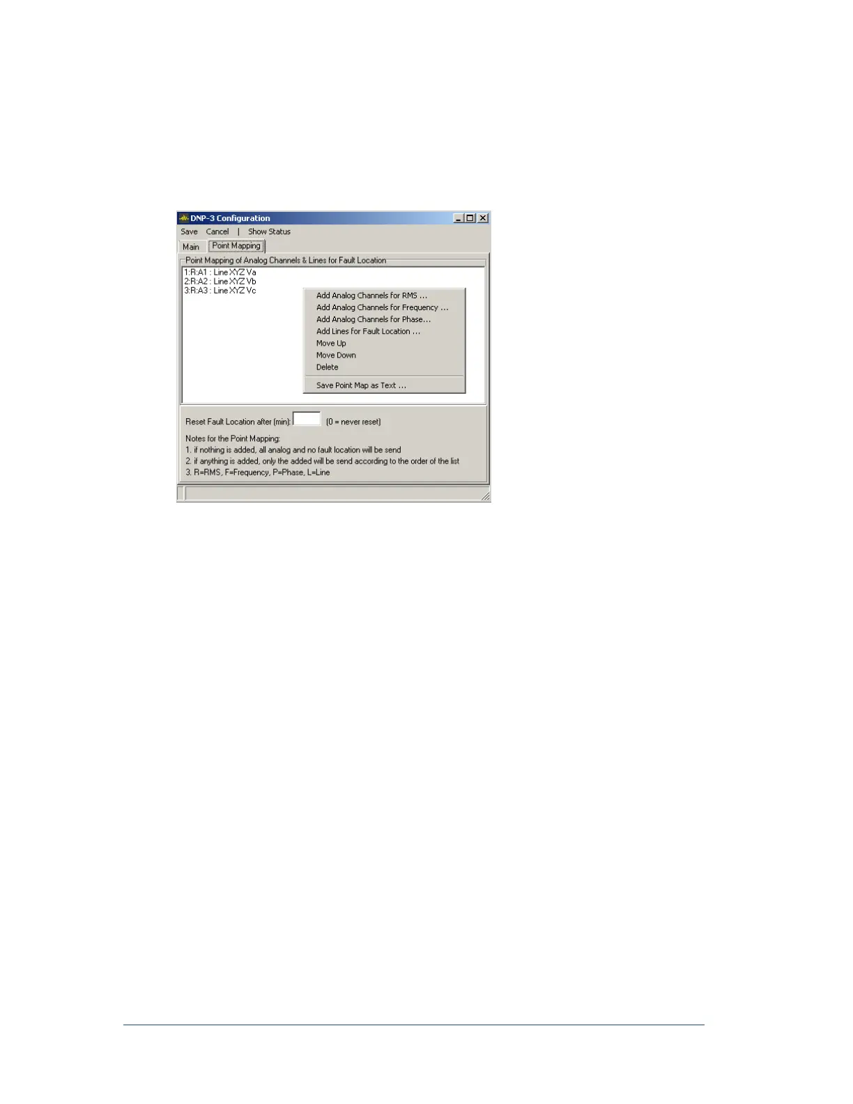
If the Point Mapping table is empty, only analog channels RMS, and no frequency, phase or fault
location will be sent, and the order for analog channels will be analog channel 1, 2, 3 and so on. If the
table is not empty, then only the ones on the table will be sent and according to the order on the table.
For fault location, the unit is in miles and is multiplied by 10 for 16-bit analog input. For example, a fault
location of 24.6 miles will be represented by 246. The fault location can be configured to be reset to 0 in
number of minutes or never reset until next valid fault location has arrived.
1. Right click in the open screen to get mapping menu
Select one of the four options for adding Channels or lines to the mapping.
Analog Channels for RMS
Analog Channels for Frequency
Analog Channels for Phase
Lines for Fault Location
Each record will be labeled with a number and type: R=RMS, F=Frequency, P=Phase, L=Line
2. Order the list by selecting one or more and click Move Up or Move Down.
3. Remove from the list by selecting one or more and click Delete.
4. You can save a Text File of the list by clicking Save Point Map as Text then browsing to the
folder you want and type a name and click OK.
To View the DNP3/Modbus Communication Status
You can view the DNP3 communication status while the APP Recorder is running.
1. In the APP Recorder window, from the Tools menu, click DNP3. The DNP-3/Modbus
Configuration Window appears as shown in Figure 50.
2. From the menu bar, click Show Status. The window appears, as shown in the following figure.